Download

1 / 53
530 likes | 659 Views
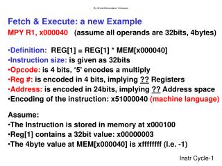
Computer Architecture and the Fetch-Execute Cycle. Memory Addressing Techniques. Learning Objectives. Explain the concepts of direct, indirect, indexed, relative addressing and immediate addressing of memory when referring to low-level languages. Memory Addressing Techniques.

E N D
Computer Architecture and the Fetch-Execute Cycle Memory Addressing Techniques
Learning Objectives • Explain the concepts of direct, indirect, indexed, relative addressing and immediate addressing of memory when referring to low-level languages.
Memory Addressing Techniques • Direct Addressing • Indirect Addressing • Indexed Addressing • Relative Addressing • Immediate Addressing
Direct Addressing • Means that the value in the address part of a machine code instruction is the address of the data. • Simple to use but does not allow access to all memory addresses as there are memory addresses larger than can be held in the address part of an instruction. • e.g. A 32-bit memory location may use 12 bits for the instruction code and 20 bits for the address of the data. • This would allow for 2^12 (= 4096) instruction codes and 2^20 (= 1 048 576) memory addresses. • However, a computer using 32-bit memory locations will have 2^32 (= 4 294 967 296) memory addresses. • So direct addressing does not allow reference to all addresses e.g. for a computer using 32-bit memory locations, addresses from 2^20 – 2^32 cannot be referred to.
Assembly Language Instructions Main memory • LDD 117 Accumulator
Assembly Language Instructions Main memory • LDD 117 Accumulator
Assembly Language Instructions Main memory • LDD 117 Accumulator
Assembly Language Instructions Main memory • LDD 117 Accumulator 11001000
Indirect Addressing • Means that the value in the address part of a machine code instruction is the address of the address of the data.
Why use indirect addressing? • Allows more memory to be accessed than direct addressing as the full size of register is used for an address. • If this value points to a location which holds nothing but an address then 2^32 locations in memory can be addressed.
Assembly Language Instructions Main memory • LDI 117 Accumulator
Assembly Language Instructions Main memory • LDI 117 Accumulator
Assembly Language Instructions Main memory • LDI 117 Accumulator
Assembly Language Instructions Main memory • LDI 117 Accumulator
Assembly Language Instructions Main memory • LDI 117 Accumulator
Assembly Language Instructions Main memory • LDI 117 Accumulator 11001111
Indexed Addressing Index Register (IR) A special register used to adjust the address part of an instruction in the CIR. The original address part of the instruction in the CIR is now changed by adding the contents of the index register (IR) to it, to give a new effective address of the data.
Indexed Addressing can be used once during one Fetch-Decode-Execute-Reset Cycle: • To reach a particular element in an array or field in a record. • IR = Offset of the required element or field from the start of the array or record. • Instruction address = Address of the start of the array or record.
Assembly Language Instructions Main memory • LDX 117 Accumulator Index Register 00000011
Assembly Language Instructions Main memory • LDX 117 Accumulator Index Register 00000011 = 3
Assembly Language Instructions Main memory • LDX 117 + 3 = 120 Accumulator Index Register 00000011 = 3
Assembly Language Instructions Main memory • LDX 117 + 3 = 120 Accumulator Index Register 00000011 = 3
Assembly Language Instructions Main memory • LDX 117 + 3 = 120 Accumulator Index Register 00000011 = 3
Assembly Language Instructions Main memory • LDX 117 + 3 = 120 Accumulator 11011100 Index Register 00000011 = 3
Indexed Addressingcan be used repeatedly To allow a number of fields in contiguous records or contiguous elements in an array to be accessed by incrementing the Index Register (IR) between each successive access instruction.
Indexed Addressing e.g. to add 5 memory locations - 1
Indexed Addressing STOP
Why use Indexed Addressing? • Why not do something similar to the high-level instruction? • NewAddress = OriginalAddress + Offset • Add NewAddress • Doing it this way would involve: • Reserving two memory addresses: • Address & Offset. • 8Fetch-Decode-Execute-Reset cycles: • Set the OriginalAddress, set the Offset, load the OriginalAddress, add Offset, store the NewAddress, access the contents of this “indirect” NewAddress, load offset, check if offset is < or > than a specified condition (number of elements required) and either loop back or stop.
Why use Indexed Addressing? • Indexed addressing avoids this: • Note that it is usual to decrement instead of incrementing as most computers have a command to test if a register is below 0, which provides a convenient method of stopping the loop. • Set the IR = Number of elements required - 1 • Access (Address of 1st element + IR) • Decrement IR by 1 • Test if IR < 0 otherwise loop back to step 2. • This only involves only 4Fetch-Decode-Execute-Reset cycles and one register (IR). • Note the IR is in the processor, not memory so no memory locations are used in indexed addressing.
Why use Indexed Addressing? • This means that the original access instruction as written in the code does not need to be modified . • Also avoids 4 additional cycles and using 2 memory locations. • Note the IR is in the processor, not memory so no memory locations are used in indexed addressing.
Why use Indexed Addressing? • Note for fields in a record then: • Set the IR = No of records required - 1 • Address in access instruction = Address of 1st record • Decrement IR by offset.
For more research: • http://www.docstoc.com/docs/21677063/INSTRUCTION-ADDRESSING-MODES
Relative Addressing • Address in the instruction is the displacement from the current instruction’s address + 1 (due to the PC being incremented) already in the PC. • Used mainly with jump instructions. • The address in the instruction is added to the value in the PC. • e.g. • The current instruction is in address 3000 and is Jump *45*, using relative addressing this means that the line wants to jump to an instruction 45 lines ahead of the next instruction (due to the PC being automatically incremented by 1 during any Fetch-Decode-Execute-Reset Cycle this means 46 lines ahead of the current instruction). • The PC will have been incremented to 3001 (ready for the next instruction) so the PC is changed to 3001+45 = 3046. • The next cycle retrieves the next instruction from there. • The program knows where the line is relative to the current instruction but not the true address – see Memory Management Presentation or next 2 slides. • Therefore allows for relocatable code (code that be moved anywhere without jump instructions etc… being affected).
+ Index Table Displacement e.g. 45 Physical Address e.g. 3001+45 = 3046
+ Physical Address e.g. 3501+131=3632 Displacement e.g. 131 Segment Index Table
Relative Addressing Can also be used to access data in addresses relative to the current instruction. The only difference is that the new “effective” address would be loaded into the MAR instead of the CIR.
RelativeVsIndexed Addressing • Similar as they both involve changing an address by addition but: • Indexed Addressing: • Changes the address in the instruction in the CIR. • Address limited to the size of the address field in the CIR, as in direct addressing. • Effective address = address in the CIR + contents of IR • Relative Addressing: • Changes the address in the PC or MAR not the address in the instruction in the CIR. • Address can be full value of the register as modified effective address is on its own in the PC or MAR. • Effective address = current instruction’s address+ 1 + value in instruction
For more research http://www.edsim51.com/8051Notes/8051/instructionSetSummary.html http://en.wikipedia.org/wiki/Addressing_modes
Immediate Addressing • Immediate addressing is so-named because the value to be stored in memory immediately follows the operation code in memory. • e.g. “Load 20” where 20 refers to a value and is loaded directly into the accumulator. • You could argue that there is no address being used at all, but there you go! • Immediate addressing is very fast since the value to be loaded is included in the instruction. • However, since the value to be loaded is fixed at compile-time it is not very flexible.