Download
1 / 17
170 likes | 317 Views
LHCb Trigger and Data Acquisition System Requirements and Concepts. Beat Jost Cern / EP on behalf of the LHCb Collaboration Presentation given at the 3 rd Workshop on Network Based Event-Building and DAQ Held October 20 th 2000 in Lyon, France. Outline. Introduction

E N D
LHCb Trigger and Data Acquisition SystemRequirements and Concepts Beat Jost Cern / EP on behalf of the LHCb Collaboration Presentation given at the 3rd Workshop on Network Based Event-Building and DAQ Held October 20th 2000 in Lyon, France
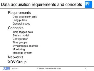
Outline • Introduction • General Trigger/DAQ Architecture • Trigger/DAQ functional components • Timing and Fast Controls • Level-1 Trigger • Readout Units/Front-End Multiplexers • Sub-Farm Architecture • Event-Building Network • Controls • Summary
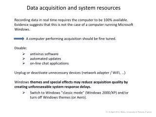
Introduction to LHCb • Special purpose experiment to measure precisely CP violation parameters in the BB system • Detector is a single-arm spectrometer with one dipole • Total b-quark production rate is ~75 kHz • Expected rate from inelastic p-p collisions is ~15 MHz • Branching ratios of interesting channels range between 10-5-10-4 giving interesting physics rate of ~5 Hz LHCb in Numbers
Trigger/DAQ Architecture LHC-B Detector Data rates VDET TRACK ECAL HCAL MUON RICH 40 MHz Level 0 Trigger 40 TB/s Level-0 Front-End Electronics Level-1 1 MHz Timing & Fast Control L0 Fixed latency 4.0 ms 1 TB/s 40 kHz L1 Level 1 Trigger LAN 1 MHz Front-End Multiplexers (FEM) Front End Links 6 GB/s Variable latency <1 ms RU RU RU Read-out units (RU) Throttle Read-out Network (RN) 6 GB/s SFC SFC Sub-Farm Controllers (SFC) Variable latency L2 ~10 ms L3 ~200 ms Control & Monitoring Storage 50 MB/s Trigger Level 2 & 3 Event Filter CPU CPU CPU CPU
TTCrx Local trigger (optional) Readout Readout Readout Supervisor Supervisor Supervisor SD1 TTCtx SD2 TTCtx SDn TTCtx L0 TTCtx L1 TTCtx Optical couplers Optical couplers Optical couplers Optical couplers TTCrx TTCrx TTCrx TTCrx FEchip FEchip FEchip FEchip FEchip FEchip FEchip FEchip FEchip FEchip FEchip FEchip FEchip FEchip L0E L0E L0E L0E ADC ADC ADC ADC TTCrx ADC TTCrx ADC ADC ADC ADC ADC TTCrx TTCrx ADC ADC FEchip FEchip FEchip FEchip FEchip Throttle OR FEchip Control Control L1 buffer L1 buffer FEchip FEchip Control L1 buffer Control L1 buffer ADC ADC ADC ADC ADC DSP ADC DSP L1E ADC L1E ADC DSP DSP L1E L1E Timing and Fast Control Clock fanout LHC clock BC and BCR • Provide common and synchronous clock to all components needing it • Provide Level-0 and Level-1 trigger decisions • Provide commands synchronous in all components (Resets) • Provide Trigger hold-off capabilities in case buffers are getting full • Provide support for partitioning (Switches, ORs) TTCrx L0 trigger L1 trigger 17 17 L1 L0 L1 L0 L0 Throttle L1 Throttle TFC switch switch switch L1 trigger system TTC system Throttle OR DAQ DAQ
CN CN CN CN SN CN CN CN CN CN CN CN CN CN CN CN CN SN CN CN CN CN CN CN CN CN CN CN SN CN CN CN CN CN CN CN CN CN CN CN SN CN CN CN CN CN CN CN CN CN CN SN CN CN CN CN CN CN CN CN CN CN CN CN SN CN CN CN CN CN CN CN Level-1 Trigger Basic Idea: Network interconnecting the computing nodes of a processor farm to the data sources • Purpose • Select events with detached secondary vertices • Algorithm • Based on special geometry of vertex detector (r-stations, -stations) • Several steps • track reconstruction in 2 dimensions (r-z) • determination of primary vertex • search for tracks with large impact parameter relative to primary vertex • full 3 dimensional reconstruction of those tracks • Expect rate reduction by factor 25 • Technical Problems: 1 MHz input rate, ~4 GB/s data rate, small event fragments, Latency restrictions
SN CN CN CN CN CN CN SN CN CN CN CN CN CN SN CN CN Computing Node SN CN CN CN CN CN y SN CN CN CN CN CN CN Source Node SN CN CN CN CN CN CN SN CN CN CN CN CN CN Level-1 Trigger (2) Implementation • ~32 sources to a network • Algorithm running in processors (~200 CPUs) • In principle very similar to DAQ, however the input rate of 1 MHz poses special problems. • Current studies centered around an SCI based torus topology • Simulation of system was done • First tests show that data can be written to SCI at 1.5 MHz Dimensional routing (first x then y). At any given time not more than one SN must send its data to a certain torus column (see matching color in the sketch). -> need for traffic-shaping x
DAQ Functional Components • Readout Units (RUs)/Front-End Multiplexers (FEM) • Multiplex input links (Slink) onto Readout Network links (RU) or Slink (FEM) • Merge input fragments to one output fragment • Subfarm Controllers (SFCs) • assemble event fragments arriving from RUs to complete events and send them to one of the CPUs connected • dynamic load balancing among the CPUs connected • Readout Network • provide connectivity between RUs and SFCs for event-building • provide necessary bandwidth (6 GB/sec sustained) • CPU farm • execute the high level trigger algorithms • execute reconstruction algorithm • Processing needs: ~100 kSI95, i.e. ~1000 processors Note: There is no central event manager Timing & Fast Control LAN Front-End Multiplexers (FEM) Front End Links 6 GB/s RU RU RU Read-out units (RU) Throttle 6 GB/s Read-out Network (RN) SFC SFC Sub-Farm Controllers (SFC) Variable latency Control 50 MB/s L2 ~10 ms & CPU CPU Storage L3 ~200 ms Monitoring Trigger Level 2 & 3 CPU CPU Event Filter
RU/FEM Architecture As FEM • 16:1 Multiplexer/EB • Minimal/No Buffering • SLink Output • no output blocking As RU • 4:1 Multiplexer/EB • significant buffering • Output to RN • possible output blocking • ~1.5 MHz sub-event building performance
Gb Ethernet 100Mb Ethernet Controls Path Sub-Farm Architecture Readout Network Gb Technology SFC Data Switch CPU Node Controls PC CPU Node Controls Switch Controls System CPU Node
‘Standard’ PC PCI Bus Local Bus Readout Network (GbE?) CPU Smart NIC ~50 MB/s ~0.5 MB/s PCI Bridge Subfarm Network (GbE) NIC Memory ~50 MB/s ~0.5 MB/s Controls Network (FEth) Control NIC SFC Architecture
Event-Building Network • Requirements • 6 GB/s sustained bandwidth • scalable • expandable • ~120 inputs (RUs) • ~120 outputs (SFCs) • affordable and if possible commercial (COTS, Commodity?) • Readout Protocol • Pure push-through protocol of complete events to one CPU of the farm • Destination assignment following identical algorithm in all RUs (belonging to one partition) based on event number • Simple hardware and software • No central control perfect scalability • Full flexibility for high-level trigger algorithms • Larger bandwidth needed (+~50%) compared with phased event-building • Avoiding buffer overflows via ‘throttle’ to trigger • Only static load balancing between RUs and SFCs
60x1GbE 60x1GbE E.g. Foundry BigIron 15000 E.g. Foundry BigIron 15000 12x10GbE 3 3 3 3 E.g. Foundry BigIron 15000 E.g. Foundry BigIron 15000 60x1GbE 60x1GbE Event-Building Activities (to date) • Studied Myrinet • Tested NIC event-building • simulated switching fabric of the size suitable for LHCbResults show that switching network could be implemented (provided buffers are added between levels of switches) • Currently focussing on xGb Ethernet • Studying smart NICs (-> Niko’s talk) • Possible switch configuration for LHCb with ~today’s technology (to be simulated...) Myrinet Simulation Multiple Paths between sources and destinations!
Master Configuration DB Storage etc. Archives, Logfiles WAN LAN CPC . . . CPC CPC CPC CPC ROC PLC Other systems (LHC, Safety, ...) PLC PLC PLC Readout system Sub-Detectors & Experimental equipment Controls System Common integrated controls system • Detector controls (classical ‘slow control’) • High voltage • Low voltage • Crates • Alarm generation and handling • etc. • DAQ controls • Classical RUN control • Setup and configuration of all components (FE, Trigger, DAQ, CPU Farm, Trigger algorithms,...) • Consequent and rigorous separation of controls and DAQ path Same system for both functions! Scale: ~100-200 Control PCs many 100s of Credit-Card PCs By itself sizeable Network! Most likely Ethernet
Summary • LHCb is a special purpose experiment to study CP violation • Triggering poses special challenges • Similarity between inelastic p-p interactions and events with B-Mesons • DAQ is designed with simplicity and maintainability in mind • Push protocol throughout the system • Simple, e.g. No central event manager in the event builder • no backward communication and definitely no lateral communication • Slightly harder bandwidth requirements on readout network (~1.5 times) • We are convinced that readout network can be realized at reasonable cost • Unified approach to Controls • Same basic infrastructure for detector controls and DAQ controls • Both aspects completely integrated but operationally independent