Download

1 / 18
180 likes | 205 Views
This study examines the nature and impacts of geomagnetically induced current (GIC) on power transformers and provides strategies for mitigating its effects. It also analyzes GIC flow patterns in both radial and complex power systems. The effectiveness of series capacitors, neutral blocking devices, and switching operations in reducing GIC is evaluated.

E N D
GIC Flow Characteristics and Mitigation Zhenhua Wang, Aster Amahatsion, Jovil Rajesh Benny Stephen, Larry Anderson
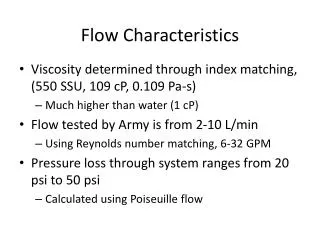
Nature of GIC • GIC is a quasi DC current induced by the interaction between space weather and earth’s magnetic field • GIC is generated by transmission lines. To form a closed circuit, transformer is the only path for GIC to return to the ground.
Nature of GIC • GIC can cause transformer half cycle saturation which links to following impacts to the power grid: • Reactive power losses • Harmonics and mis-operation of protective measures • Transformer overheating
Effective GIC The concept of effective GIC is used to measure GIC impact level to power transformers. For wye ground-delta connected transformers, effective GIC is equal to the GIC current flow through wye winding. For wye ground-wye ground transformers and auto transformers, since both high and low side windings carry GIC, transformer turns ratio needs to be considered to reflect the overall effect of DC current on both windings. Equation (1) can be used to calculate per phase effective GIC for all three transformer connections: (1)
TPL-007-1 This study is based on the assumption of uniform geoelectric field. It is aimed to provide guidance for R7 of TPL-007-1 and give an insight of system vulnerability for planning purpose. R7. Each responsible entity, as determined in Requirement R1, that concludes, through the GMD Vulnerability Assessment conducted in Requirement R4, that their System does not meet the performance requirements of Table 1 shall develop a Corrective Action Plan addressing how the performance requirements will be met. • Typically AEP will implement following for mitigations: • Equipment hardening • Operation Procedures
GIC Flow in Radial Systems • System edge always exhibits high effective GIC level • Kirchhoff's Current Law indicates substations inside the radial system experience lower level of effective GIC
GIC Flow in Radial Systems • The radial system example indicates: • High GIC level does not mean high effective GIC level • Effective GIC is more sensitive to the system topology instead of the strength of geoelectric field • It is necessary to summarize a more general form of GIC flow character for assessing system vulnerability and mitigation
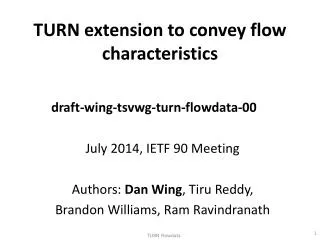
GIC Flow in Complex Systems • One transmission line
GIC Flow in Complex Systems • Two transmission lines • GICs generated by two circuits are flowing at the same direction will add up at the substation • GICs generated by two circuits are flowing at opposite directions will cancel each other at the substation
GIC Flow in Complex Systems • More than two transmission lines - GIC Active Circuit • GIC carried by a transmission line which does not have a matching peer in the opposite quadrant have to immediately return to ground through wye grounded transformers in the substation. • These transmission lines are GIC active since there is no cancellation for GIC generated by them. • By counting the number of GIC active circuits, one could approximately rank the severity of effective GIC level for a particular system topology.
Mitigation Strategies • Series capacitor • Due to the nature of capacitor, series capacitor could completely block GIC generation of the transmission line it attached to. • From the stand point of GIC flow, series capacitor could either increase or decrease the number of GIC active circuit according to the system topology. Eliminating GIC generation ≠Reducing effective GIC
Mitigation Strategies • Table 1. Transformer effective GIC per phase (Amps, 140 degree orientation) Table 2. Transformer effective GIC per phase (Amps, 90 degree orientation)
Mitigation Strategies • Transformer neutral blocking devices (NBD) Table 3. Impact of Neutral Blocking Device (Amp) Location of NBD
Mitigation Strategies Table 4 NBD Effects on System E-GIC
Mitigation Strategies • Neutral blocking devices change the number of GIC active circuit which is the reason of “shifting” effective GIC to substation 3. • For auto transformers, neutral blocking devices are only able to block GIC in common winds. Auto transformers still exhibit reactive power losses and harmonics associated with GIC. • The effectiveness of neutral blocking device is very limited if the deployment is in a small scale. Neutral Blocking ≠ Reducing effective GIC
Mitigation Strategies • Switching operation • Branch switching <-> series capacitors • Switching on/off a transmission line may reduce the number of GIC Active Circuit therefore reduce the effective GIC and vice versa. • Transformer switching <-> NBD devices • Switching on/off a transformer may produce a new system edge or shift GIC to other locations. Switching operation = Reducing effective GIC?
Conclusion • The concept of GIC active circuit is an effective way to analyze the GIC flow pattern. • Simply blocking the GIC flow path may not be a efficient mitigation for reducing the effective GIC • The length of transmission circuits and substation grounding resistance should be taken into consideration in the future.