Download
1 / 27
280 likes | 394 Views
Discover the history, properties, and utilization of ELF waves in wireless communication, focusing on their use by the US Navy for submarine communication. Learn about antenna technologies and the unique challenges and benefits of utilizing ELF frequencies.

E N D
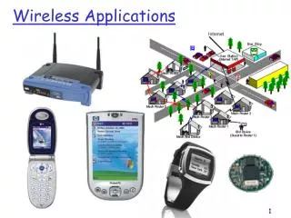
Wireless Applications of the ELF Range EECS 4390: Wireless and Mobile Networks Robert Hannan Laura Bott James Jones
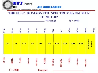
Frequency Classifications ELF extremely low frequency 3Hz to 30Hz 100'000km to 10'000 km SLF super-low frequency 30Hz to 300Hz 10'000km to 1'000km ULF ultra-low frequency 300Hz to 3000Hz 1'000km to 100km VLF very low frequency 3kHz to 30kHz 100km to 10km LF low frequency 30kHz to 300kHz 10km to 1km MF medium frequency 300kHz to 3000kHz 1km to 100m HF high frequency 3MHz to 30MHz 100m to 10m VHF very high frequency 30MHz to 300MHz 10m to 1m UHF ultrahigh frequency 300MHz to 3000MHz 1m to 10cm SHF super-high frequency 3GHz to 30GHz 10cm to 1cm EHF extremely high frequency 30GHz to 300GHz 1cm to 1mm
Extra Low Frequency • < 1 Hz – 300 Hz • Not commonly used in communication • Due to large wavelength, permeates large objects and water
History of ELF • Nikola Tesla 1900 • Inventor of AC current • First to work with ELF transmission • Purpose was to Transmit power wirelessly in Colorado Springs • Was the first to build an ELF transmitting antenna
Utilization or ELF waves • Wireless Communication • Used by the US Navy for submarine communication • Tesla briefly transmitted large amounts of power using ELF • Non-destructive testing • Earthquake Prediction
Properties of Large Wavelengths • Reflection and scattering are relatively negligible for the fact that the propagating wavelength will be much larger than the object it impinges upon • Experience very little path loss
For Example… A 100 MHz displays a 56.2 dB path loss in free space 10 log (4*3.14*100,000/3) = 112.437 dB compared to 30 Hz wave with a -9 dB path loss 10 log (4*3.14*100,000/10,000,000) = -18.02 dB
Utilization of ELF in Communication • Primarily used by U.S. Navy for communication with submerged submarines. • The extremely high electrical conductivity of seawater shields submarines from most electromagnetic communications. • Signals in ELF range, however, can penetrate much more deeply. • Low transmission rate of most ELF communications limits their use as communication channels.
US Navy ELF Communication Network • Has Transmitting antennas in Wisconsin and the Upper Peninsula of Michigan • Signal is transmitted into the atmosphere where it is enclosed between the Earth and the Ionosphere • Signal can be transmitted around the world at a frequency of 76Hz • They use SQUID and Tether antennas for signal reception
ELF for Communication • Advantages • Penetrate virtually any object • It can Travel Long distances with little path loss • Disadvantages • Though it travels at the speed of light it has a very low data rate • The size of receiving and transmitting antenna is inversely proportional to the frequency
Problem Statement • Improve the sensitivity of a receiving antenna • Improve the relative size of the antenna • Make an economic receiving antenna
Tether and Ground antenna • Measure E-field • Too long • Wavelength of signal at 8 Hz • Basic antenna Theory says the antenna should be at least half the wavelength of the signal • That equates to over 100 miles in wire. • Impractical because of size and the amount of noise it would be exposed to over that distance
Electric Field Antennas • Too long • Sensitive to noise and interference • Very unpractical • Magnetic field antennas (sensors) is a better choice
Various Antennas Ball antenna stands over 5’ tall Stanford’s Elf Magnetic Field Antenna Coil Antenna about 2 m in length
Magnetic Sensors • Can be small and very sensitive • Exhibit a usable signal-to-noise ratio • Of interest: Coil antennas
SQUID Super Conducting Quantum Interference Device - Sensitivity threshold magnitude: 10-14 T
Characteristics of the SQUID • Frequency detection range is from DC up to 1kHz • Sensitivity threshold of 10^-14 Tesla • Measurements are based on the change in the H field based on one flux quantum\ *Flux quantum is the amount of magnetic flux from the earth’s magnetic field passing through an area the size of a human red blood cell.
SQUID Conclusions • Advantages • Very Sensitive to ELF signals • Can be made light weight and portable • Disadvantages • Has to be Cryogenically cooled • Very sensitive to environmental noise • The driving electronics are extremely complex • Expensive and requires regular maintenance
Coil Antenna • High Permeable Ferrite Core • 1,000 turns of wire • Sensitivity of 1 pT (10^-12) • Frequency Range of < 1Hz-1kHz • Active Circuit developed by Dr. John Sutton
Active Circuit • Patented by Dr. John Sutton of Goddard • Allows the coil to attract and bend the incoming magnetic waves • Small coil absorbs energy from large portion of magnetic wave
Comparison of Normal coil antenna to coil antenna using active circuitry
Loop Antenna Easy to fabricate Inexpensive Low maintenance Sensitivity of 1 pico Tesla (10^-12) Frequency Range of 1Hz to about 1 kHz Squid Antenna Complicated driving electronics Highly susceptible to environmental noise Cryogenic cooling needed Sensitivity of 10^-14 Tesla Frequency Range of DC to about 1kHz Comparison of Two Antenae
Conclusions • Coil antenna can be used for ELF reception • Using the Introduced circuitry we can improve on the Navy’s current receiving antenna • The coil antenna will decrease maintenance and cost of production while maintaining the required frequency range and sensitivity • Actually the low sensitivity will decrease the amount of environmental interference
What We DID? • Researched and became familiar with Navy communication system and antenna design • Using developed circuitry we propose a transition for the US Navy to use a loop antenna using an active circuit as opposed to the SQUID or Tether.