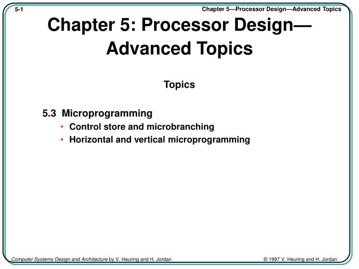

Chapter 5: Processor Design—Advanced Topics
E N D
Presentation Transcript
Chapter 5: Processor Design—Advanced Topics Topics 5.3 Microprogramming • Control store and microbranching • Horizontal and vertical microprogramming
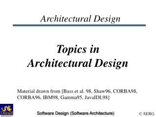
M a s t e r S t r t W a i t D o n e O p C o d e I R O t h e r s i g n a l s f r o m c l o c k t h e d a t a p a t h D e c o d e r . . . C O N n = 0 C l o c k i n g l o g i c . . . l d a d d s h c b r E n a b l e S t e p g e n e r a t o r T 0 r T 1 I n t e r r u p t s C o u n t l n C o n t r o l e C o n t r o l t T 2 a n d o t h e r n . . . s t e p s i g n a l u e x t e r n a l o 4 T 4 d e c o d e r e n c o d e r C . . . s i g n a l s . . . . . . T n – 1 . . . . . . L o a d R e s e t G e n e r a t e d c o n t r o l s i g n a l s . . . P A P R G W r C D C o a a u i i o D t t n u t Control Unit Implemented as Hardware - Hardwired Control Unit . Fig 4.11 Control Unit Detail with Inputs and Outputs
Microprogramming: Basic Idea • Recall control sequence for 1-bus SRC Step Concrete RTN Control Sequence T0 MA PC: C PC + 4; PCout, MAin, INC4, Cin, Read T1 MD M[MA]: PC C; Cout, PCin, Wait T2 IR MD; MDout, IRin T3 A R[rb]; Grb, Rout, Ain T4 C A + R[rc]; Grc, Rout, ADD, Cin T5 R[ra] C; Cout, Gra, Rin, End • Control unit job is to generate the sequence of control signals • Hardwired approach uses an FSM implemented in hardware to generate these sequences • An alternate solution is to build a smaller “computer” to perform this function - microcode engine
The Microcode Engine • A computer to generate control signals is much simpler than an ordinary computer • At the simplest, it just reads the control signals in order from a read-only memory • The memory is called the control store • A control store word, or microinstruction, contains a bit pattern telling which control signals are true in a specific step • The major issue is determining the order in which microinstructions are read
Microcoded Control Unit Microsequence generator (computer) microaddress Microstore (memory) microbranch information (if needed) microinstructions (data from memory) Decoder (optional) ... Generated Control Signals Cin OR Gra PCin MAin AND PCout Microcode Engine: Basic Implementation • Some information in microstore can be used to alter control flow of microsequence generator (microbranches) • Optional decoder can be used to expand microcode to control larger number of control points (horizontal vs. vertical microcode)
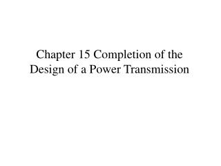
C k C C s O t h e r I R O p c o d e P L A S e q u e n c e r ( c o m p u t e s E x t e r n a l 2 s t a r t a d d r ) s o u r c e n 4 1 M u x I n c r e m e n t n P C n C o n t r o l s t o r e n k m I R B r a n c h c o n t r o l B r a n c h C o n t r o l s i g n a l s a d d r e s s P C , e t c . o u t Microcode Engine: More Details Fig 5.16 Block Diagram of Microcoded Control Unit • Microinstruction has branch control, branch address, and control signal fields • Microprogram counter can be set from several sources to do the required sequencing
Parts of the Microprogrammed Control Unit • Since the control signals are just read from memory, the main function is sequencing • This is reflected in the several ways the PC can be loaded • Output of incrementer—PC + 1 • PLA output—start address for a macroinstruction • Branch address from instruction • External source—say for exception or reset • Micro conditional branches can depend on condition codes, data path state, external signals, etc.
Contents of a Microinstruction . Microinstruction format • Main component is list of 1/0 control signal values • There is a branch address in the control store • There are branch control bits to determine when to use the branch address and when to use PC + 1 Control signals Branch control Branch address Ain Cout End PCin MAin PCout
Fig 5.17 The Control Store • Common instruction fetch sequence • Separate sequences for each (macro) instruction • Wide words
1 0 1 • • • 1 0 0 0 1 1 0 0 0 0 1 1 0 0 0 0 0 0 1 0 2 • • • 0 1 0 0 0 0 1 0 0 0 0 0 1 0 0 0 0 0 1 0 3 • • • 0 0 1 0 0 0 0 1 0 0 0 0 0 0 0 0 0 0 2 0 0 • • • 0 0 0 1 0 0 0 0 1 0 0 0 0 0 0 1 0 0 2 0 1 • • • 0 0 0 1 0 1 0 0 0 0 0 0 0 1 0 0 1 0 2 0 2 • • • 0 1 0 0 0 0 0 0 0 1 0 0 0 0 1 0 0 1 Tbl 5.2 Control Signals for the add Instruction . • Addresses 101–103 are the instruction fetch • Addresses 200–202 do the add • Change of control from 103 to 200 uses a kind of branch
Uses for branching in the Microprogrammed Control Unit • (1) Branch to start of code for a specific inst. • (2) Conditional control signals, e.g. CON PCin • (3) Looping on conditions, e.g. n 0 ... Goto6 • Conditions will control branches instead of being ANDed with control signals • Microbranches are frequent and control store addresses are short, so it is reasonable to have a branch address field in every instruction
Illustration of branching Control Logic • We illustrate a branching control scheme by a machine having condition code bits N and Z • Branch control has 2 parts: • (1) selecting the input applied to the PC and • (2) specifying whether this input or PC + 1 is used • We allow 4 possible inputs to PC • The incremented value PC + 1 • The PLA lookup table for the start of a macroinstruction • An externally supplied address • The branch address field in the instruction word
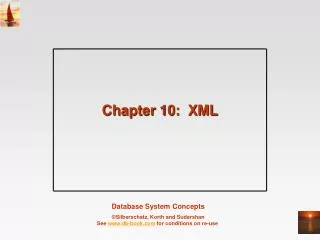
Z N S e q u e n c e r P L A 2 E x t e r n a l a d d r e s s 2 2 2 4 – 1 M u x 2 I n c r . P C 2 B r a n c h a d d r e s s C o n t r o l s t o r e 0 0 0 0 0 0 0 C o n t r o l s i g n a l s 2 4 4 1 0 2 M u x c o n t r o l B r U n M u x C t l S e l e c t B r N o t Z 0 0 I n c r e m e n t P c B r Z B r N o t N 0 1 P L A B r N 1 0 E x t e r n a l a d d r e s s 1 1 B r a n c h a d d r e s s Fig 5.18 Branching Controls in the Microcoded Control Unit • 5 branch conditions • NotN • N • NotZ • Z • Unconditional • To 1 of 4 places • Next instruction • PLA • External address • Branch address
. C o n t r o l B r a n c h S i g n a l s A d d r e s s B r a n c h i n g a c t i o n 0 0 0 0 0 0 0 • • • X X X N o n e — n e x t i n s t r u c t i o n 0 1 1 0 0 0 0 • • • X X X B r a n c h t o o u t p u t o f P L A 1 0 0 0 1 0 0 • • • X X X B r i f Z t o E x t e r n . A d d r . 1 1 0 0 0 0 1 • • • 3 0 0 B r i f N t o 3 0 0 ( e l s e n e x t ) 1 1 0 0 0 1 0 0 • • • 0 2 0 6 B r i f N t o 2 0 6 ( e l s e n e x t ) 1 1 1 0 0 0 0 • • • 2 0 4 B r t o 2 0 4 Some Possible branches Using the Illustrated Logic (Refer to Tbl 5.3) • If the control signals are all zero, the instruction only does a test • Otherwise test is combined with data path activity
Horizontal versus Vertical Microcode Schemes • In horizontal microcode, each control signal is represented by a bit in the instruction • In vertical microcode, a set of true control signals is represented by a shorter code • The name horizontal implies fewer control store words of more bits per word • Vertical code only allows RTs in a step for which there is a vertical instruction code • Thus vertical code may take more control store words of fewer bits
Fig 5.19 A Somewhat Vertical Encoding A L U R e g i s t e r - o u t o p s f i e l d f i e l d • Scheme would save (16 + 7) - (4 + 3) = 16 bits/word in the case illustrated I R F 5 F 8 4 3 4 – 1 6 d e c o d e r 3 – 8 d e c o d e r 1 6 A L U 7 R e g o u t c o n t r o l c o n t r o l s i g n a l s s i g n a l s
P C V e r t i c a l c o n t r o l s t o r e H o r i z o n t a l P C c o n t r o l s t o r e D a t a I P C M n p a t h n t o 2 n d e c o d e r i C c A n 4 i o n u t P C o u t M A i n I n c 4 C i n Fig 5.20 Completely Horizontal and Vertical Microcoding
Saving Control Store Bits with Horizontal Microcode • Some control signals cannot possibly be true at the same time • One and only one ALU function can be selected • Only one register out gate can be true with a single bus • Memory read and write cannot be true at the same step • A set of m such signals can be encoded using log2m bits (log2(m + 1) to allow for no signal true) • The raw control signals can then be generated by a k to 2k decoder, where 2k m (or 2k m + 1) • This is a compromise between horizontal and vertical encoding
A Microprogrammed Control Unit for the 1-Bus SRC • Using the 1-bus SRC data path design gives a specific set of control signals • There are no condition codes, but data path signals CON and n = 0 will need to be tested • We will use branches BrCON, Brn = 0, and Brn 0 • We adopt the clocking logic of Fig. 4.14 • Logic for exception and reset signals is added to the microcode sequencer logic • Exception and reset are assumed to have been synchronized to the clock
O t h e r B r C o n t r o l A d d r . A c t i o n s A d d r . S i g n a l s 1 0 0 0 0 0 0 0 0 0 1 1 X X X • • • M A P C : C P C + 4 ; 1 0 1 0 0 0 0 0 0 0 0 0 • • • X X X M D M [ M A ] : P C C ; 1 0 2 0 1 1 0 0 0 0 0 0 X X X • • • I R M D ; P C P L A ; 2 0 0 0 0 0 0 0 0 0 0 0 X X X • • • A R [ r b ] ; 2 0 1 0 0 0 0 0 0 0 0 0 X X X • • • C A + R [ r c ] ; 2 0 2 1 1 1 0 0 0 1 0 0 1 0 0 • • • R [ r a ] C : P C 1 0 0 ; Tbl 5.4 The add Instruction . • Microbranching to the output of the PLA is shown at 102 • Microbranch to 100 at 202 starts next fetch
Getting the PLA Output in Time for the Microbranch • For the input to the PLA to be correct for the branch in 102, it has to come from MD, not IR • An alternative is to use see-through latches for IR so the opcode can pass through IR to PLA before the end of the clock cycle
See-Through Latch Hardware for IR So PC Can Load Immediately • Data must have time to get from MD across Bus, through IR, through the PLA, and satisfy PC set up time before trailing edge of S
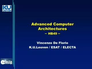
C O N n = 0 E x c e p t i o n R e s e t n 4 0 0 S e q u e n c e r n 0 0 0 B r a n c h a d d r e s s P L A 1 0 E x t e r n a l a d d r e s s 2 2 x u M 2 1 4 – 1 M u x 2 – 2 2 2 I n c r e m e n t P C 2 n 2 M u x c o n t r o l B r U n B r C O N B r N 0 B r N = 0 E n d Fig 5.21 SRC Microcode Sequencer
Tbl 5.6 Somewhat Vertical Encoding of the SRC Microinstruction
Other Microprogramming Issues • Multiway branches: often an instruction can have 4–8 cases, say address modes • Could take 2–3 successive branches, i.e. clock pulses • The bits selecting the case can be ORed into the branch address of the instruction to get a several way branch • Say if 2 bits were ORed into the 3rd and 4th bits from the low end, 4 possible addresses ending in 0000, 0100, 1000, and 1100 would be generated as branch targets • Advantage is a multiway branch in one clock • A hardware push-down stack for the PC can turn repeated sequences into subroutines • Vertical code can be implemented using a horizontal engine, sometimes called nanocode