Download
1 / 41
540 likes | 954 Views
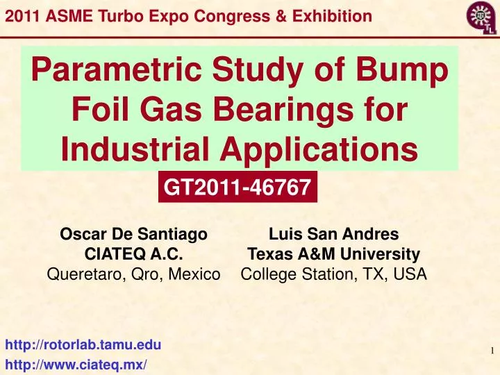
2011 ASME Turbo Expo Congress & Exhibition. Parametric Study of Bump Foil Gas Bearings for Industrial Applications. GT2011-46767. http://rotorlab.tamu.edu. http://www.ciateq.mx/. Oil-Free Bearings for Turbomachinery. Justification

E N D
2011 ASME Turbo Expo Congress & Exhibition Parametric Study of Bump Foil Gas Bearings for Industrial Applications GT2011-46767 http://rotorlab.tamu.edu http://www.ciateq.mx/
Oil-Free Bearings for Turbomachinery Justification Current advancements in vehicle turbochargers and midsize gas turbines need of proven gas bearing technology to procure compact units with improved efficiency in an oil-free environment. Also, Oil-freeturbomachinery and subsea compression are among major focuses in modern energy industry. DOE, DARPA, NASA interests range from applications as portable fuel cells (< 60 kW) in microengines to midsize gas turbines (< 250 kW) for distributed power and hybrid vehicles. • Gas Bearingsallow • weight reduction, energy and complexity savings • higher temperatures, without needs for cooling air • improved overall engine efficiency
Available Bearing Technologies Magnetic bearings • Low to medium temperatures • Moderate loads • Need control systems • Need back-up bearings • Long history of operation in some specific industrial applications www.skf.com, 2011 www.synchrony.com, 2011 Schweitzer/Maslen 2009 • Current Magnetic Bearing solution is expensive and even more expensive (and difficult) to make it reliable
Available Bearing Technologies Flexure Pivot Bearing Herringbone grooved bearing NICH Center, Tohoku University • Precision fabrication process • Low load capacity and stiffness and little damping GT 2004-53621 GAS BEARINGS Gas Foil Bearing • Oil-Free • NO DN limit • Low friction and power loss • Thermal management AIAA-2004-5720-984 Rolling element bearings • Low temperatures • Low DN limit (< 2 M) • Need lubrication system AIAA 2004-4189 PowerMEMS 2003
Microturbomachinery as per IGTI ASME Paper No. GT2002-30404 Drivers: deregulation in distributed power, environmental needs, increased reliability & efficiency Distributed power (Hybrid Gas turbine & Fuel Cell), Hybrid vehicles Automotive turbochargers, turbo expanders, compressors, Honeywell, Hydrogen and Fuel Cells Merit Review Max. Power ~ 250 kWatt International Gas Turbine Institute
Micro Gas Turbines 60kW MGT www.microturbine.com Microturbine Power Conversion Technology Review, ORNL/TM-2003/74. Cogeneration systems with high efficiency • Multiple fuels (best if free) • 99.99X% Reliability • Low emissions • Reduced maintenance • Lower lifecycle cost Hybrid System : MGT with Fuel Cell can reach efficiency > 60% Ideal to replace reciprocating engines. Low footprint desirable
Examples of commercial applications • Micro Turbines • Capstone of California • Turbo chargers • Honeywell “on the race”
Examples of commercial applications • Industrial Air Compressors • Samsung’s successful Micro Turbo Master line of compressors feature gas foil bearings • Pressures up to 130 psig • Powers up to 0.13 MW • Samsung has another line (Turbo Master) of air compressors with pressures up to 300 psig and power up to 2.4 MW (~20x larger). Run on TPJB.What’s next ?? www.samsungtechwin.com, 2011
MTM – Needs, Hurdles & Issues Largest power to weight ratio, Compact & low # of parts High energy density Reliability and efficiency, Low maintenance Extreme temperature and pressure Environmentally safe (low emissions) Lower lifecycle cost ($ kW) High speed Materials Manufacturing Processes & Cycles Fuels Rotordynamics & (Oil-free) Bearings & Sealing Coatings: surface conditioning for low friction and wear Ceramic rotors and components Automated agile processes Cost & number Low-NOx combustors for liquid & gas fuels TH scaling (low Reynolds #) Best if free (bio-fuels)
Gas Bearings for Oil-FreeMTM • Advantages of gas bearings over oil-lubricated bearings • Process gas is cleaner and eliminates contamination by buffer lubricants • Gases are more stable at extreme temperatures and speeds (no lubricant vaporization, cavitation, solidification, or decomposition) • Gas bearing systems are lower in cost: less power usage and small friction, enabling savings in weight and piping Gas Bearings Must Be Simple!
Ideal gas bearings for MTM Load Tolerant – capable of handling both normal and extreme bearing loads without compromising the integrity of the rotor system. Simple – low cost, small geometry, low part count, constructed from common materials, manufactured with elementary methods. High Rotor Speeds – no specific speed limit (such as DN) restricting shaft sizes. Small Power losses. Good Dynamic Properties – predictable and repeatable stiffness and damping over a wide temperature range. Reliable – capable of operation without significant wear or required maintenance, able to tolerate extended storage and handling without performance degradation. +++ Modeling/Analysis (anchored to test data) available
Gas Bearings for MTM What are the needs? • Make READY technology for industrial application by PUSHING development to • make out of the shelf item with proven results for a wide range of applications; • engineered product with well known manufacturing process; • known (verifiable) performance with solid laboratory and field experiences
Gas Bearings Research at TAMU See References at end Thrust: Investigate conventional bearings of low cost, easy to manufacture (common materials) and easy to install & align. Combine hybrid (hydrostatic/hydrodynamic) bearings with low cost coating to allow for rub-free operation at start up and shut down Major issues:Little damping, Wear at start & stop,Nonlinear behavior (subsync. whirl)
Gas Bearing Research at TAMU 2001/2 - Three Lobe Bearings 2003/4 - Rayleigh Step Bearings 2002-09 - Flexure Pivot Tilting Pad Bearings 2004-11:Bump-type Foil Bearings 2008-12:Metal Mesh Foil Bearings Stability depends on feed pressure. Stable to 80 krpm with 5 bar pressure Worst performance to date with grooved bearings Stable to 93 krpm w/o feed pressure. Operation to 100 krpm w/o problems. Easy to install and align. Industry standard. Reliable but costly. Models anchored to test data. Cheap technology. Still infant. Users needed See References at end
Gas Foil Bearings Advertised advantages:high load capacity (>20 psig), rotordynamically stable, tolerance of misalignment and shocks
Gas Foil Bearings – Bump type • Series of corrugated foil structures (bumps) assembled within a bearing sleeve. • Integrate a hydrodynamic gas film in series with one or more structural layers. Applications:APUs, ACMs, micro gas turbines, turbo expanders • Reliable • Tolerant to misalignment and debris, also high temperature • Need coatings to reduce friction at start-up & shutdown • Damping from dry-friction and operation with limit cycles
Foil Bearings (+/-) • Increased reliability: load capacity (< 20 psi) • No lubricant supply system, i.e. reduce weight • High and low temperature capability (> 1,000 C) • No scheduled maintenance • Tolerate high vibration and shock load. Quiet operation • Endurance:performance at start up & shut down (lift off speed) • Little test datafor rotordynamic force coefficients & operation with limit cycles (sub harmonic motions) • Thermal managementfor high temperature applications (gas turbines, turbochargers) • Predictive models lack validation for GFB operation at HIGH TEMPERATURE
Theoretical basis • Solve Reynolds equation for compressible flow (isothermal case). • Coupled to bump metal sheet deformation (non-linear stiffness and damping). • Iterative solution to find bearing equilibrium position. • Perturbation analysis to find dynamic performance (frequency-dependent stiffness and damping coefficients).Refs: San Andrés (2009), Arghir (2004), Iordanoff (1999), Heshmat (1992)
The computational program • Windows OS and MS Excel 2003 (minimum requirements) • Fortran 99 Executables for FE underspring structure and gas film analyses. Prediction of forced – static & dynamic- performance. • Excel® Graphical User Interface (US and SI physical units). Input & output (graphical) • Compatible with XLTRC2 and XLROTOR codes Code: XL_GFBTHD
Graphical User Interface Worksheet: Shaft & Bearing models (I)
Graphical User Interface Worksheet: Shaft & Bearing models (II)
Graphical User Interface Worksheet: Top Foil and Bump Models
Graphical User Interface Worksheet: Foil Bearing (Operation and Results)
Results • Example bearing (Ref [3]): • Bump unit area stiffness lowers as bump pitch increases • Bump unit area stiffness increases with foil thickness
Results Measured load capacity (Ref [3]) Current predictions, constant load of 31 psi 31 psi Calibration point 1 Calibration point 2 • Benchmarking with independent experiments – Generation 1 bearing (Ref [3]). • Used to find practical limit of film thickness
Results • Base bearing (Ref [3]):
Rule of thumb for design From observations of bump stiffness and bearing performance predictions: • Bearing scaling: use Della Corte´s rule:W ~ N L D^2 • Bump scaling:Knew = Korig / f ; f is de diameter scale factor
Application example • Industrial compressor for injection service • 8 impellers, 640 lb rotor • Re-configured rotor – move bearings INBOARD of gas seals • Use larger diameter at bearing location Bearing characteristics Expected speed range:3 to 20 krpm 13-15 krpm MCOS most typical
Application - rotordynamics Linear stability analysis Predicted stiffness range Compressor can´t cross these speeds (requires more damping) 5th
Observations • Conceptually, scaled gas foil bearings can support an industrial, flexible rotor. • Re-location of bearings is necessary to decrease unit load, but it is feasible in the compressor working environment. • Rotor-bearing system requires additional damping to control shaft vibration at critical speeds.
Closure Dominant challenges for gas bearing technology: • Low gas viscosity requires minute clearances to generate load capacity. • Damping & rotor stability are crucial • Inexpensive coatings to reduce drag and wear • Bearing design & manufacturing process well known • Adequate thermal management to extend operating envelope into high temperatures
Closure Other pressing challenges for gas bearing technology: intermittent contact and damaging wear at startup & shut down, and temporary rubs during normal operating conditions Current research focuses oncoatings (materials), rotordynamics (stability) & high temperature (thermal management) Need Low Cost & Long Life Solution!
Oil-Free Bearings for Turbomachinery References
References Foil Bearings
References Foil Bearings
References Metal mesh foil bearings
Acknowledgments Learn more: http://rotorlab.tamu.edu Thanks to NSF (Grant # 0322925) NASA GRC (Program NNH06ZEA001N-SSRW2), Capstone Turbines, Inc., Honeywell Turbocharging Systems, Korea Institute of Science and Technology (Dr. Tae-Ho Kim) Foster-Miller, MiTI, TAMU Turbomachinery Research Consortium (TRC) CIATEQ A.C.