Download
1 / 25
252 likes | 509 Views
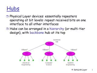
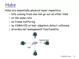
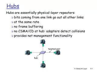
twisted pair. hub. Hubs. Hubs are essentially physical-layer repeaters: bits coming from one link go out all other links at the same rate no frame buffering no CSMA/CD at hub: adapters detect collisions provides net management functionality. Manchester encoding. Used in 10BaseT

E N D
twisted pair hub Hubs Hubs are essentially physical-layer repeaters: • bits coming from one link go out all other links • at the same rate • no frame buffering • no CSMA/CD at hub: adapters detect collisions • provides net management functionality 5: DataLink Layer
Manchester encoding • Used in 10BaseT • Each bit has a transition • Allows clocks in sending and receiving nodes to synchronize to each other • no need for a centralized, global clock among nodes! • Hey, this is physical-layer stuff! 5: DataLink Layer
Gbit Ethernet • uses standard Ethernet frame format • allows for point-to-point links and shared broadcast channels • in shared mode, CSMA/CD is used; short distances between nodes required for efficiency • uses hubs, called here “Buffered Distributors” • Full-Duplex at 1 Gbps for point-to-point links • 10 Gbps now ! 5: DataLink Layer
5.1 Introduction and services 5.2 Error detection and correction 5.3Multiple access protocols 5.4 Link-Layer Addressing 5.5 Ethernet 5.6 Interconnections: Hubs and switches 5.7 PPP 5.8 Link Virtualization: ATM Link Layer 5: DataLink Layer
Interconnecting with hubs • Backbone hub interconnects LAN segments • Extends max distance between nodes • But individual segment collision domains become one large collision domain • Can’t interconnect 10BaseT & 100BaseT hub hub hub hub 5: DataLink Layer
Switch • Link layer device • stores and forwards Ethernet frames • examines frame header and selectively forwards frame based on MAC dest address • when frame is to be forwarded on segment, uses CSMA/CD to access segment • transparent • hosts are unaware of presence of switches • plug-and-play, self-learning • switches do not need to be configured 5: DataLink Layer
switch hub hub hub Forwarding 1 3 2 • How do determine onto which LAN segment to forward frame? • Looks like a routing problem... 5: DataLink Layer
Self learning • A switch has a switch table • entry in switch table: • (MAC Address, Interface, Time Stamp) • stale entries in table dropped (TTL can be 60 min) • switchlearns which hosts can be reached through which interfaces • when frame received, switch “learns” location of sender: incoming LAN segment • records sender/location pair in switch table 5: DataLink Layer
Filtering/Forwarding When switch receives a frame: index switch table using MAC dest address if entry found for destinationthen{ if dest on segment from which frame arrivedthen drop the frame else forward the frame on interface indicated } else flood forward on all but the interface on which the frame arrived 5: DataLink Layer
Switch example Suppose C sends frame to D address interface switch 1 1 1 2 3 A B E G 3 2 hub hub hub A I F D G B C H E • Switch receives frame from from C • notes in bridge table that C is on interface 1 • because D is not in table, switch forwards frame into interfaces 2 and 3 • frame received by D 5: DataLink Layer
Switch example Suppose D replies back with frame to C. address interface switch 1 1 2 3 1 A B E G C hub hub hub A I F D G B C H E • Switch receives frame from from D • notes in bridge table that D is on interface 2 • because C is in table, switch forwards frame only to interface 1 • frame received by C 5: DataLink Layer
switch hub hub hub Switch: traffic isolation • switch installation breaks subnet into LAN segments • switch filters packets: • same-LAN-segment frames not usually forwarded onto other LAN segments • segments become separate collision domains collision domain collision domain collision domain 5: DataLink Layer
Switches: dedicated access A • Switch with many interfaces • Hosts have direct connection to switch • No collisions; full duplex Switching: A-to-A’ and B-to-B’ simultaneously, no collisions C’ B switch C B’ A’ 5: DataLink Layer
More on Switches • cut-through switching: frame forwarded from input to output port without first collecting entire frame • slight reduction in latency • combinations of shared/dedicated, 10/100/1000 Mbps interfaces 5: DataLink Layer
Institutional network mail server to external network web server router switch IP subnet hub hub hub 5: DataLink Layer
Switches vs. Routers • both store-and-forward devices • routers: network layer devices (examine network layer headers) • switches are link layer devices • routers maintain routing tables, implement routing algorithms • switches maintain switch tables, implement filtering, learning algorithms 5: DataLink Layer
Summary comparison 5: DataLink Layer
5.1 Introduction and services 5.2 Error detection and correction 5.3Multiple access protocols 5.4 Link-Layer Addressing 5.5 Ethernet 5.6 Hubs and switches 5.7 PPP 5.8 Link Virtualization: ATM Link Layer 5: DataLink Layer
Point to Point Data Link Control • one sender, one receiver, one link: easier than broadcast link: • no Media Access Control • no need for explicit MAC addressing • e.g., dialup link, ISDN line • popular point-to-point DLC protocols: • PPP (point-to-point protocol) • HDLC: High level data link control (Data link used to be considered “high layer” in protocol stack! 5: DataLink Layer
PPP Design Requirements [RFC 1557] • packet framing: encapsulation of network-layer datagram in data link frame • carry network layer data of any network layer protocol (not just IP) at same time • ability to demultiplex upwards • bit transparency: must carry any bit pattern in the data field • error detection (no correction) • connection liveness: detect, signal link failure to network layer • network layer address negotiation: endpoint can learn/configure each other’s network address 5: DataLink Layer
PPP non-requirements • no error correction/recovery • no flow control • out of order delivery OK • no need to support multipoint links (e.g., polling) Error recovery, flow control, data re-ordering all relegated to higher layers! 5: DataLink Layer
PPP Data Frame • Flag: delimiter (framing) • Address: does nothing (only one option) • Control: does nothing; in the future possible multiple control fields • Protocol: upper layer protocol to which frame delivered (eg, PPP-LCP, IP, IPCP, etc) 5: DataLink Layer
Byte Stuffing • “data transparency” requirement: data field must be allowed to include flag pattern <01111110> • Q: is received <01111110> data or flag? • Sender: adds (“stuffs”) extra < 01111110> byte after each < 01111110> data byte • Receiver: • two 01111110 bytes in a row: discard first byte, continue data reception • single 01111110: flag byte 5: DataLink Layer
Byte Stuffing flag byte pattern in data to send flag byte pattern plus stuffed byte in transmitted data 5: DataLink Layer
PPP Data Control Protocol Before exchanging network-layer data, data link peers must • configure PPP link (max. frame length, authentication) • learn/configure network layer information • for IP: carry IP Control Protocol (IPCP) msgs (protocol field: 8021) to configure/learn IP address 5: DataLink Layer