Download

1 / 15
150 likes | 329 Views
Status of electronics for NuTel prototype. Yuri Velikzhanin (yuri@hep1.phys.ntu.edu.tw) NuTel TV meeting, June 13 (Friday), 2003. RAM. Preamp. FADC. RAM. PMT. Trigger. DAQ. Trigger. Preamp. PMT. FADC. RAM. RAM. Schematics of new electronics. Mirror. 2 RAM x 256 x 16 per channel.

E N D
Status of electronics forNuTel prototype Yuri Velikzhanin (yuri@hep1.phys.ntu.edu.tw) NuTel TV meeting, June 13 (Friday), 2003
RAM Preamp. FADC RAM PMT Trigger DAQ Trigger Preamp. PMT FADC RAM RAM Schematics of new electronics Mirror 2 RAM x 256 x 16 per channel UV filter 10 bit x 40 MHz FPGA Stop Detector pair UV filter Stop 16-channels preamplifier Hamamatsu 8x8 PMT 32 – channels DCM (Data Collection Module) in cPCI
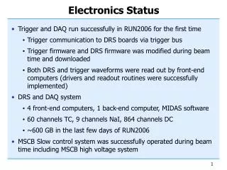
Main modifications during last month • Change design from VME onto Compact PCI (cPCI) due we need fast readout speed for making a second-level software trigger. • Delete all interconnections for trigger signals due we don’t need statistics (uniformity, isotropy…) – there will be around one event per year. Loosing less 1% only! • Use two triggers: first-level hardware trigger like logical OR of triggers inside all DCM, and second-level software trigger. One Data collection module processes signals from 4x8 pixels (half of MPMT) from one detector. • Use 25nS (one clock) gate for trigger logic due most of signal are inside one clock (from our simulations).
readout readout stop stop RAM buffer 256 256 Old version: two cycle buffers per channel with depth 256. x8 Marked memory cells for readout P C I FIFO 1Kx16 1 256 2 FIFO 1Kx16
Expected layout of DCM J3 ? x2 sides L O C A L B U S J2 ADC ADC ADC Config. CPLD Flash memory ADC main FPGA ADC LVDS ADC trigger P3 ? Trigger FPGA trigger ADC ADC clock J1 P2 ADC ADC cPCI bus connectors ADC main FPGA PLX PCI9054 ADC P1 ADC ADC ADC ADC x2 sides
40 MHz with good 0-1 time ratio r e g r e g r e g MUX divider 80 MHz external 40 MHz comparator Clocking/timing DCM x 32 (200) 40 MHz oscillator Trigger FPGA to ADC to ADC FIFO FPGA FIFO FPGA terminators ? 80 MHz, 40 MHz 32x2 outputs ? Global Clocking module Global Clocking module Clock distributor module 80 MHz, 40 MHz ~2 km. away 80 MHz oscillator 80 MHz oscillator 80 MHz oscillator
Trigger How to calculate N p.e./1 clock AN+1 Change in amplitude due new photoelectrons: ΔA = AN+1 – 15/16AN N = ΔA / gain AN ΔA 15/16AN Schematics of firmware (inside FPGA) ΔAN-1 = AN-1–15/16AN-2 AN AN-1 ADC Reg. Reg. Reg. – – >>4 Reg. Reg. 15/16AN-2 1/16AN 1/16AN-1 15/16AN-1
Trigger Time interval for trigger From simulation > 90% of signal comes during one ADC clock, so time interval will be one clock – 25 nS. There will be used two thresholds logic: Schematics of firmware (inside main FPGA) Programmable High-level threshold (individual for every channel) HLT comparator Reg. ΔAN Reg. To trigger logic LLT Reg. comparator Programmable Low-level threshold (individual for every channel)
Trigger Trigger array of one DCM
DAQ configuration C P U T R I G G E R D C M D C M D C M D C M D C M B R I D G E D C M D C M D C M D C M D C M D C M B R I D G E D C M D C M D C M D C M D C M Ethernet C P U T R I G G E R D C M D C M D C M D C M D C M B R I D G E D C M D C M D C M D C M D C M D C M B R I D G E D C M D C M D C M D C M D C M Not fixed (discussable) !!!
1 1 1 1 1 1 1 1 256 256 256 256 256 256 256 256 2 2 2 2 2 2 2 2 Data flux inside main FPGA event number d a t a f r o m A D C to local bus x16 FIFO 1Kx16 FIFO size: if 4 time slots: 1024/8/4 = 32 events! But we need to add event number: 1024/8/5 = 25 events!
Data flux inside one DCM J3 ? L O C A L B U S J2 main FPGA D15-D00 Config. CPLD Flash memory Ch.1-8 main FPGA D15-D00 LVDS P3 ? Ch.9-16 Trigger FPGA main FPGA D31-D16 J1 P2 cPCI bus connectors Ch.17-24 D31-D00 PLX PCI9054 main FPGA D31-D16 P1 Ch.25-32
Possible data flux inside one chassis DMA RAM Bank#1 from cPCI DMA RAM Bank#2 CPU Second-level trigger DMA RAM Bank#3 to Ethernet DMA RAM Bank#4
(moved ~one month later due cPCI design instead VME) Schedule for electronics • Before August 1: have 2 DCM and 4 new preamplifiers • August-September: debugging first iteration, hope a final • October-December: making a final firmware, two Trigger modules (simple), software… • January: Mass production • February – March: Mass debugging + start integration test • End of March - beginning of April: end of the first period of NuTel project Problems • Optics – main problem now • MPMT – we have only 11 pieces, need 16, could Palermo people give as some pieces? When? If not – we need to bye. We’ll need its before February. • HV power supply is in VME. Already have one (for 8 MPMT), need another one.