Download
1 / 15
150 likes | 259 Views
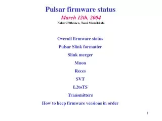
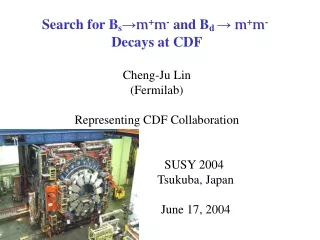
L2toTS Status and Phase-1 Plan and Pulsar S-LINK Data Format Cheng-Ju Lin Fermilab L2 Trigger Upgrade Meeting 03/12/2004. L2toTS Pulsar Board. TS. TS broadcast L2A/L2R to all front-end crates. Send L2 trigger decision to trigger supervisor. Receive L2 trigger decision from PC.

E N D
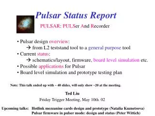
L2toTS Status and Phase-1 Plan and Pulsar S-LINK Data Format Cheng-Ju Lin Fermilab L2 Trigger Upgrade Meeting 03/12/2004
L2toTS Pulsar Board TS TS broadcast L2A/L2R to all front-end crates Send L2 trigger decision to trigger supervisor Receive L2 trigger decision from PC b0xft00 b0cot00 b0fcal05 • Phase-I implementation is straightforward: • - only need to deal with one PC, • - firmware is simple. • Phase-II implementation: • - need to handle 4 PC, • - L2toTS may also need to keep track of L2 scalers, • - Some trigger prescale could be done in L2toTS board.
L2toTS Testing Status • We have setup a mini-DAQ system in the test-stand room to send random L1/L2 • triggers (“sparky II”) to all 8 test-stand crates. TS broadcast L1 and L2 decision to test-stand crates TS FRED preFRED PMT L1A/R L1A Trigger Bits tstmuon1 L2A tstsvt1 tstl2trg1 Trigger Bits L2A/R • Accomplished 3 goals with this setup: • - tested FRED Pulsar link • - tested Pulsar TS hand-shaking • (millions of hand-shakings without problem) • - “Sparky” setup can be used to drive the • test-stand crates at high rate with random • L1 and L2 triggers. L2toTS
Mini-DAQ (supports 8 test-stand crates) Pulsar (GL2) RXPT TXPT TS FRED (GL1) preFRED Greg F., Andrew M. , Michael S. and Bill B. did a tremendous job getting the different boards to live happily under one roof.
Summer Commissioning • With the Sparky setup in the test-stand room, we can do most of the • commissioning work in the test-stand. • Pulsar TS link is well tested in the test-stand room. Will need to verify • that it can still talk to the trigger supervisor in the trigger room (some • differences in the signal lines between trigger room and test-stand room • TS setup). • The input path (PCPulsar) have already been tested by Kristian et al. • So far we’ve tested the input and output stages separately. The remaining • task is to write and test the firmware for passing the L2 trigger decision • from the input stage to the output stage. • We’ll try to design the internal stage firmware to be compatible • with 4 CPU Phase-2 configuration.
Testing L2toTS Firmware (internal stage) “L2 CPU” L2toTS TS SLINK Receiver SLINK Transmitter (sending L2A/R) Milestones to meet: - Have “internal stage” firmware ready in early April (time scale is determined by Sakari’s availability). - Use the existing Merger firmware to transmit L2A/R to the L2toTS board. - Test and debug the firmware in the test-stand by the end of April. - Start testing the full PCPulsarTS chain in May. - Move to the trigger room in early June. - Monitoring and diagnostic code (eg. TrigMon) will need to be ready before the full scale integration with the rest of the Pulsar boards.
Pulsar pre-processors ALL DATA TRANSMISSION IN PULSAR SYSTEM ARE IN CERN SLINK FORMAT L1 muon L1 XTRP L1 trigger muon SLINK L2 CAL (CLIST/Iso) PreFred TS PC cluster merger SVT ShowMax (RECES) L2toTS electron SVT SLINK Upstream input merger
S-Link Global Data Format (from Pulsar to Level-2 CPU) • The S-Link data blocks are self-describing, • The data block from each path is enclosed by a header and a trailer word, • The bit structure for the header/trailer words is universal: • Format version #, • Data source (0=global, 1=muon, 2=SVT, 3=Cluster, etc…), • Region ID bits is reserved for each data path (eg. RECESS path can • use Region ID to identify which Pulsar board the data comes from), • L2 buffer # and bunch counter are in the header. • The trailer word contains the error flag bits and the data size (# of SLINK words) 24-31 20-23 18-19 10-17 2-9 bits 0-1 Format version Data source Region ID Reserved Bunch Counter Buff# SLINK Header SLINK data goes here (32bit-wide word) SLINK Trailer Data size (16 bits) Error flags (16 bits) 32 bits
CLUSTER (ISO+CLIST+SUMET) • The cluster board process “ISOLIST”, “CLIST”, and SUMET data. Format version Data source Region ID Reserved Bunch Counter Buff# SUM Et Bits from preFRED L1 TOF Bits from preFRED (optional) CLIST Header CLIST Data CLIST Trailer ISOLIST Header Isolist Data ISOLIST Trailer Data size (16 bits) Error flags (16 bits) 32 bits
Isolation S-Link Data Format • Minimum of 4 32-bit words are needed for each isolation cluster. Format version Data source Region ID Bunch Counter Buff# Reserved Header Spare[24..31] #Sum Spare[21..22] Overflow Spare[15] Buffer# Data bit Pass# Isolation Cluster#1 Et Sum 2 [16..31] Et Sum 1 [0..15] Et Sum 4 [16..31] Et Sum 3 [0..15] Either spare or Et Sum 6 [16..31] Et Sum 5 [0..15] Trailer Data size (16 bits) Error flags (16 bits) 32 bits • Pass # [0..1] same as CAL Cluster data. Isolation trigger only uses pass 0 and 1, • [2..6] and [10..14] are defined for the seed tower, • Data bit [7] 1=diagnostic, 0=real data, • Buffer# [8..9] Level 2 buffer #, • Overflow[16..20] overflow bits for the 5 Et sums (bit 16 is for Et Sum 1), • #Sum [23] 0= 5 Et Sums, 1= more than 5 Et sums.
Cluster S-Link Data Format Format version Data source Region ID Bunccounter Buff# Reserved Spare [28..30] Had Over- flow [31] Had Energy Sum [16..17] EM Over- flow [15] Spare [12..14] EM Energy Sum [0..11] Spare [24..30] Valid Bit [31] L2 Buffer # [20..21] Cluster [10..14] Pass # [22..23] Cluster [15..19] Number of towers in cluster [0..9] Two SLINK words/CLIST cluster Data size (16 bits) Error flags (16 bits) 32 bits • Two SLINK words per CLIST cluster • Cluster and are defined for the seed tower, • Pass # corresponds to the different seed and shoulder thresholds, • valid bit is set to zero if some hardware condition is found that could cause • the crates to report wrong cluster data (eg. Multiple crates reporting the • presence of a seed at the same time).
L1/XTRP/MUON SLINK Package • Keep muon+XTRP data structure the same as RunIIa • Append L1 trigger bits (64 bits) at the beginning of the package Format version Data source Region ID Reserved Bunch Counter Buff# Level 1 Trigger Decision bits 0-31 Level 1 Trigger Decision bits 32-63 Spare [29..31] Reserved for Stereo data [23..28] EP [21] Short bit [20] Isolation bit [19] pT bin [12..18] Track [0..11] EE [22] One32-bit word per XFT track Spare [23..31] EE [22] EP [21] Pulsar FPGA # [20] Pulsar Mezz Card # [19] Pulsar Ch# [17..18] TCMD Word # [12..16] Trigger Bits Part I [0..11] Spare [23..31] EE [22] EP [21] Pulsar FPGA # [20] Pulsar Mezz Card # [19] Pulsar Ch# [17..18] TCMD Word # [12..16] Trigger Bits Part II [0..11] Two 32-bit word per non-zero muon wedge Data size (16 bits) Error flags (16 bits) 32 bits
SVT Path • The SVT data format is identical to the current TL2D format. • For each SVT track, we need to send two 32-bit words: Format version Data source Region ID Bunch Counter Buff# Reserved Spare [29..31] Sign of impact Parameter [28] Absolute value of impact parameter [19..27] Zout [16..18] Zin [13..15] Track [0..12] Spare [30..31] Track-fitter error Summary [29] XFT Linker ID [20..28] 2 of fit [9..19] Sign of pT Bin [8] Absolute value of pT Bin [0..7] Two 32-bit word per SVT track Data size (16 bits) Error flags (16 bits) 32 bits
RECESS SLINK Format • RECESS SLINK fromat is different from the earlier incarnation since we are • not zero-suppressing RECESS data for Phase I • We will use the same format as TL2D Format version Data source Region ID Reserved Bunch Counter Buff# Trigger Bits for wedge West phi=0 (high eta) Trigger Bits for wedge West phi=0 (low eta) Trigger Bits for wedge West phi=1 (high eta) Trigger Bits for wedge West phi=1 (low eta) Trigger Bits for wedge West phi=23 (high eta) Trigger Bits for wedge West phi=23 (low eta) Trigger Bits for wedge East phi=0 (high eta) Trigger Bits for wedge East phi=0 (low eta) Trigger Bits for wedge East phi=1 (high eta) Trigger Bits for wedge East phi=1 (low eta) Trigger Bits for wedge East phi=23 (high eta) Trigger Bits for wedge East phi=23 (low eta) Data size (16 bits) Error flags (16 bits) 32 bits