Download
1 / 4
50 likes | 185 Views
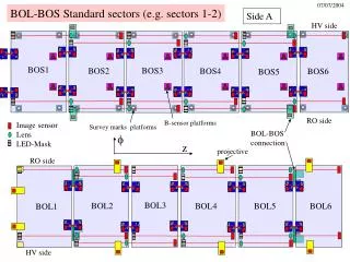
This document outlines the specifications and functionalities of the BOL-BOS surveying system, focusing on the integration of various components such as image sensors, lenses, and LED masks. It details the relationship between different sector areas, including HV and RO sides, and the significant survey marks utilized across the platforms. The system enhances precision in projective mapping with sophisticated rotational adjustments and sector configurations. Understanding these components will facilitate improved accuracy and efficiency in surveying processes.

E N D
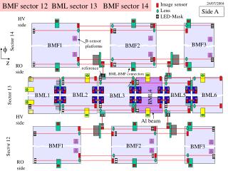
f BOL-BOS Standard sectors (e.g. sectors 1-2) Side A HV side BOS1 BOS3 BOS2 BOS4 BOS6 BOS5 RO side B-sensor platforms Image sensor Lens LED-Mask Survey marks platforms BOL-BOS connection z projective RO side BOL3 BOL2 BOL5 BOL6 BOL4 BOL1 HV side
BOL-BOS Standard sectors (e.g. sectors 1-2) HV side Lines rotated by 180o BOS-1 BOS1 BOS-2 BOS2 RO side Side A Side C RO side BOL-1 BOL-2 BOL1 BOL2 HV side Z=0
f BOL-BOS Standard sectors (e.g. sectors 1-2) Side C HV side BOS-1 BOS-3 BOS-2 BOS-4 BOS-6 BOS-5 RO side B-sensor platforms Survey marks platforms Image sensor Lens LED-Mask BOL-BOS connection z projective RO side BOL-3 BOL-2 BOL-5 BOL-6 BOL-4 BOL-1 HV side
Survey platform BOL-BOS Standard sectors BOS BOL-BOS Connection B-sensor praxial BOL Projective RASNIK