Image Sensor Pipeline
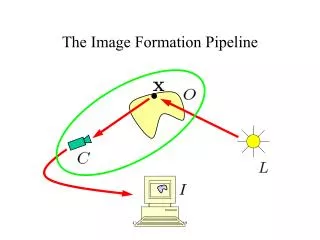
Image Sensor Pipeline. Purpose. The objective of this presentation is to describe the image processing algorithms of Digital Camera. Most of the algorithms along the data path will be described.


Image Sensor Pipeline
E N D
Presentation Transcript
Purpose • The objective of this presentation is to describe the image processing algorithms of Digital Camera. Most of the algorithms along the data path will be described. • The intended audiences include algorithm designers, software programmers, IC engineers, application engineers, and project managers as well.
Purpose • Interpolation • Bad pixel • Option black • Histogram • Exposure • White Balance • Shadow • Color Correction(Color Matrix) • Distortion
Black level with G1/G2 filter This function allows user to adjust the black level so that blacks appear as true blacks. Formula: R’ = R + BL_R_OFFSET G1’ = G1 + BL_G1_OFFSET + α*R G2’ = G2 + BL_G2_OFFSET + β*B B’ = B + BL_B_OFFSET where BL_R_OFFSET, BL_G1_OFFSET,BL_G2_OFFSET, BL_B_OFFSET, α, β are configurable parameters.
The image from sensor may have noise and dead pixels. This module can do noise cancellation and DPC at the same time. DPD/DPC and Noise Reduction diff40 = abs(p4-p0); diff41= abs(p4-p1); diff42 = abs(p4-p2); diff43 = abs(p4-p3); diff45 = abs(p4-p5); diff46 = abs(p4-p6); diff47 = abs(p4-p7); diff48 = abs(p4-p8); if((diff40>dpc_th) && (diff41>dpc_th) && (diff42>dpc_th) && (diff43>dpc_th) && (diff44>dpc_th) && (diff45>dpc_th) && (diff46>dpc_th) && (diff47>dpc_th)) Is_dead = 1; else is_dead = 0;
If it is a dead pixel, do dead pixel cancellation (DPC) DV = abs(2*p4-p1-p7); DH = abs(2*p4-p3-p5); DDL = abs(2*p4-p0-p8); DDR = abs(2*p4-p2-p6); if((DV<=DH)&&(DV<=DDL)&&(DV<=DDR)) new = (pix1+pix7+1)/2; else if((DH<DV)&&(DH<=DDL)&&(DH<=DDR)) new = (pix3+pix5+1)/2; else if((DDL<DH)&&(DDL<DV)&&(DDL<=DDR)) new = (pix0+pix8+1)/2; else new = (pix2+pix6+1)/2;
If current pixel is not dead pixel, do noise cleaning DV2 = abs(2*p4-p1-p7); DH2 = abs(2*p4-p3-p5); DDL2 = abs(2*p4-p0-p8); DDR2 = abs(2*p4-p2-p6); if ((DV2<=DH2)&&(DV2<=DDL2)&&(DV2<=DDR2)) avg = (p1+p4+p7) / 3; var = abs(p1-avg) + abs(p4-avg) + abs(p7-avg); else if((DH2<DV2)&&(DH2<=DDL2)&&(DH2<=DDR2)) avg = (p3+p4+p5) / 3; var = abs(p3-avg) + abs(p4-avg) + abs(p5-avg); else if((DDL2<DV2)&&(DDL2<DH2)&&(DDL2<=DDR2)) avg = (p0+p4+p8) / 3; var = abs(p0-avg) + abs(p4-avg) + abs(p8-avg); else avg = (p2+p4+p6) / 3; var = abs(p2-avg) + abs(p4-avg) + abs(p6-avg); if ( it is noise ) output = avg ; //? else output = p4 ;
Digital Gain There are two types of digital gain: global digital gain and R/G/B digital gain. The digital gain control is implemented on the input RGB Bayer pattern stream. All the pixel data (R, G and B) are multiplied by a digital global gain. The higher the global gain is, the brighter the image is. The global gain is used to adjust image brightness in Auto Exposure (AE) function. Different from digital global gain, digital RGB gains affect RGB pixel separately. Different color channel uses different gain value, so there are three gain values for R, G and B pixels, respectively. Digital RGB gains are used in Auto White Balance (AWB) function. Implementation: R’ = R * R_gain * Global_gain; G’ = G * G_gain * Global_gain; B’ = B * B_gain * Global_gain;
This module is used to compensate for the shading effect, which causes the image intensity to get darker on the outer range of the image. We will apply a different gain value for each different (x, y) position in the image. The algorithm works on Bayer image, and works separately on R/G/B channel. LensShadingCorrection(Vignetting)
Vignetting Vignetting
CFA Interpolation In Bayer format, each pixel has only one of R/G/B values. By CFA interpolation, each pixel will have complete R/G/B values. Interpolation of G at R/B location if (DH < DV) else Interpolation of G at B location can be done on the corresponding formula of B values.
CFA Interpolation Interpolation of G at R/B location Interpolation of G at B location can be done on the corresponding formula of B values.
CFA Interpolation Interpolation of R at B location Interpolation of B at R location can be done on the corresponding formula of B values.
Color correction is done using a color matrix and it compensates color deviation due to color filtering and sensing circuits. Color Correction
RGB Gamma Correction The transfer function of most CRT displays produces an intensity that is proportional to some power (referred to as gamma) of the signal amplitude. As a result, high-intensity ranges are expanded and low-intensity ranges are compressed.
RGB to YCbCr • The conversion uses this formula: • Formula 3:RGB range: 0-255; YCbCr range: 0-255 • Floating-point: • Fixed-point:
Edge Extraction and Sharpness Edge extraction is done on Y channel, and will be used for image sharpening. To calculate one pixel, a 3x5 filter is used.
Edge Extraction and Sharpness The edge map (EM) is further modified through a lookup table (EMLUT). EMLUT is constructed as following: The modified edge map is then added back to the Y channel. That is, Y’ = Y + EMLUT(x).
Edge Extraction and Sharpness When –x1 < x ≤ x1, we think x is the noise, not the edge. There are two methods to calculate the Y value in this range: one is Y = Y – m2x, the other is Y = Avg. DDH = abs(2*Ym,n – Ym,n-1 – Ym, n+1) ; DDV = abs(2*Ym,n – Ym-1,n – Ym+1,n) ; DDL = abs(2*Ym,n – Ym-1,n-1 – Ym+1,n+1) ; DDR = abs(2*Ym,n – Ym-1,n+1 – Ym+1,n-1) ; Find the minimum of then Avg takes the value of that direction.
Edge Extraction and Sharpness To avoid over-shoot on edges, The Y’ is further modified as the following: Find the minimum of the 15 Y’s, denoted by Ymin, and the maximum of the 15 Y’s, denoted by Ymax. if ( Y’ >= Ymax ) Y_out = Ym,n + ( (Y’ – Ymax) >> clip_bits ) else if ( Y’ < Ymin ) Y_out = Ym,n + ( (Y’ – Ymin) >> clip_bits )
False Color Suppression False color suppression is done on U, V channel.Y is not changed, U, V may be changed by false color suppression. Implementation: 1. get YUV422 data; 2. get edge on Y channel; 3. edge = abs(edge); 4. get temp by clipping the edge into [edge_min, edge_max]; Where edge_min and edge_max are user-programmable registers.
u_gain v_gain 1 0 edge_min edge_max edge False Color Suppression • calculate u_gain and v_gain: • u_gain = K_edge*(edge_max - temp); • v_gain = K_edge*(edge_max - temp); • where K_edge=65536/(edge_max - edge_min) ; • 6. do false color suppression on U, V channel when edge is larger than edge_min: • temp_u=(u_gain*(temp_u-128))/65536+128; • temp_v=(v_gain*(temp_v-128))/65536+128; • if edge is less than or equal to edge_min, just output u, v directly. • 7. clip u, v into [0, 255] and output.
BacklightingDetection and Compensation 1. Detection The shape of histogram is very special in backlight condition. Two peaks lie on the two sides of the histogram: one on the low light side, and the other on the high light side. According to this fact, we may detect the backlight condition. To detect Backlighting, we need histogram information , the mean brightness of the whole image (maybe weighted), iWinYmean and the mean brightness of 16 windows WinYmean[0] ~ WinYmean[15]; When the following adaptive condition is satisfied, it is regarded as in backlight condition: if(int_Sum_White_Rate*(iThresHold+int_Sum_Black_Rate)*20>=(BackLight_White_Thres*iThresHold*iThresHold)&& iWinYmeanMin<BackLight_WinMin_Thres) m_iBackLight = TRUE;
BacklightingDetection and Compensation 2. Compensation When the backlight is detected, and the following adaptive condition is satisfied, it is regarded as needn’t add ET time or sensor gain or digital gain or all: if(int_Sum_Black_Rate*(iThresHold+int_Sum_White_Rate)*32<(Compensate_Black_Thres*iThresHold*iThresHold)||iWinYmean>Compensate_WinMean_Thres||int_Sum_White_Rate>((iThresHold*Compensate_White_Thres)>>4)||iWinYmeanMin>Compensate_WinMinMean_Thres) m_iBkLNeedAddET = FALSE;
Brightness Input: Y, U, V in the range of [0, 255], as source image BRIGHTNESS, in the range of [-128, 127], as brightness adjustment Output: Y, U, V in the range of [0, 255] Implementation: define CLIP255(x) ((x>255)?255:((x<0)?0:x)) Y’ = CLIP255(Y + BRIGHTNESS); U’ = U; V’ = V; r
Contrast Input: Y, U, V in the range of [0, 255], as source image Output: Y’, U’, V’, in the range of [0, 255] Parameters: CONTRAST, in the range of [1, 63] Y_OFFSET, in the range of [-128, 127] Implementation: define CLIP255(x) ((x>255)?255:((x<0)?0:x)) Y’ = CLIP255(((Y*CONTRAST)>>5) + Y_OFFSET); U’ = CLIP255((((U-128)*CONTRAST)>>5)+128); V’ = CLIP255((((V-128)*CONTRAST)>>5)+128);
Hue Input: YUV422 data, Y, U and V are in the range of [0, 255]. Register Hue_sin and Hue_cos are in the range of [-256, 256] Hue angle, within the range of [-45, 45] for case 2. Output: YUV422 data, Y, U and V are in the range of [0, 255]. Implementation: If U and V fall out of [0, 255], clipping operation is applied as following: Clipping(x) = (x<0) ? 0 : ( (x>255)?255:x )
Saturation Input: YUV422 data, Y, U and V are in the range of [0, 255]. Output: YUV422 data, Y, U and V are in the range of [0, 255]. Parameter: Saturation ratio K, within the range of [0, 2]. Formula: If U and Vfalls out of [0, 255], clipping operation is applied as following: Clipping(x) = (x<0) ? 0 : ( (x>255)?255:x )
Auto Expose The luminance of the image changes when the environment varies. In order to keep the luminance in the given range, we must adjust exposure time (ET) of the sensor. If the ET is small, changing ET by one unit (one flickering period) can make the brightness of image change much. In order to make the brightness of image change smoothly, digital global gain is combined with ET adjustment
Auto Expose An image is divided into 16 windows with different weights. Ymean of the frame and Ymean of the 16 windows are calculated as described below.:
Banding (fliker) 1/60 60Hz AC 1/120 Energy Integration time must be integer of bank 1/120 ,2/120….. N/120 , Example: if exposure line =1.5 bank=1.5/120 sec 積分面不一樣, 發生banding
Auto White Balance When the white paper moves from one light source to another light source, an image sensor sees different colors under different conditions. Similarly, when a digital camera is moved from outdoors (sunlight) to indoor fluorescent (or incandescent) light conditions, the color in the image shifts. To correct for light source color-temperature changes, the balance among red, green and blue has to be shifted. This “white balancing” is performed by the algorithm below.
Auto White Balance The number (Counter) of the pixels which satisfy the following conditions and their sums (Rsum, Gsum and Bsum)) of red, green and blue are calculated along with image data stream. YbotReg<Y<YtopReg Abs(I)<ItopReg Abs(Q)<QtopReg To deal with the issue of big region of uniform color, we will add the following judgment if (Counter>=TH_GRAY_COUNT) //there is enough valid gray pixels To update RGain, BGain to adjust AWB else //there is not enough gray pixels Keep the Rgain, BGain of the last frame.
Auto White Balance The average value (AwbRmean, AwbGmean and AwbBmean) of the tricolor is calculated by the following formulas: AwbRmean=Rsum/Counter AwbGmean=Gsum/Counter AwbBmean=Bsum/Counter RDiff = abs( AwbRmean-AwbGmean ) BDiff = abs( AwbBmean-AwbGmean ) Based on these differences, Rgain and Bgain will be updated. AWB range control register (AWB threshold1, AWB threshold2, AWB gain step) will control this operation.
Auto White Balance 0 AWB threshold1 AWB threshold2 Rstep = 0 Rstep = 1 Rstep = AwbStep RgainReg – Rstep ( AwbRmean>AwbGmean) RgainNew = RgainReg + Rstep ( AwbRmean<AwbGmean) BgainReg – Bstep ( AwbBmean>AwbGmean) BgainNew = BgainReg + Bstep ( AwbBmean<AwbGmean)
Other ISP Models Motion Detection Temporal Noise Reduction Auto Focus …………
色彩品质评估 (Photography – Electronic Still Picture Imaging) ISO 12231: 1997 名詞定義與解釋 ISO 12232 :1998 ISO Speed 曝光時間與速度 ISO 12233 : 解析度的測試 ISO /FDIS 14525 :光電轉換函數的量測(OECF) ISO/DIS 12234-1 : Part1 : removable memory reference model ISO/DIS 12234-2 : Part2 :影像檔格式– TIFF/EP ISO/CD 15739 : 雜訊量測Noise Measurements ISO/WD 16067 : 空間解析度的量測Part 1: Scanners for reflective media ISO/WD 17321 : 測試條件與色彩轉換(如:測試色稿、光源與色彩空間轉換) ISO 15740 :影像轉換協定Picture Transfer Protocol(PTP) 参见国家标准《数字终端图像及视频传输特性技术要求和测试方法》