Dynamically Variable Blade Geometry for Wind Energy
This presentation explores the innovative approach of dynamically variable blade geometry in wind turbines to optimize energy production by adapting to changing wind speeds. We delve into the experimental design, simulation, and optimization of blade parameters such as pitch, chord, and twist. With a focus on improving power output through morphing blades, we present results showing a significant performance enhancement compared to fixed blades. Our findings indicate that variable twist has the greatest impact on turbine performance, achieving consistent improvements over existing pitch control systems.


Dynamically Variable Blade Geometry for Wind Energy
E N D
Presentation Transcript
Dynamically Variable Blade Geometry for Wind Energy Greg Meess, Michael Ross Dr. Ephrahim Garcia Laboratory for Intelligent Machine Systems AIAA Regional Student Conference Boston University April 23-24, 2010
Goal: Increase wind turbine energy output by morphing blade shape to match changing wind speeds. Pitch Chord Twist
Outline • Motivation • Experimental Design • Airfoil Generation • Simulation • Optimization • Results • Geometry • Power output
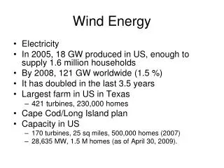
Motivation • Wind turbines are constantly increasing in size • Power output is proportional to rotor swept area • The largest turbines cannot be built on land • Blades are designed for higher wind speeds • Maximize rated power • Turbine spends little time operating at rated power • Little focus on low wind speeds • Variable Pitch http://www.terramagnetica.com/2009/08/01/why-are-wind-turbines-getting-bigger/
Problem Parameterization • Blade Element Momentum (BEM) Theory is used • Turbine has operating regime between 4 m/s and 20 m/s • 4 m/s is lower limit of current turbines • Fixed speed generator of 60 rpm • Rotations vary from 30 to 120 rpm. • Rayleigh Distribution is used to assess annual power output • Chord, twist, and camber are examined Vestas V90 power output vs. wind speed Sample wind speed Rayleigh distribution
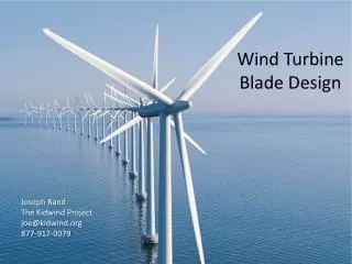
Airfoil Generation • NACA XX12 Series • Leading edge, trailing edge follow NACA equations • Flexible panels connect to leading edge, rest on trailing edge • As chord extends/retracts, panels keep airfoil profile • XFOIL Simulation • CL, CD data collected for angles of attack between -10° and 45° NACA 2412 original, fully extended, and fully retracted shapes Sample data from XFOIL for modified shapes
Turbine Performance Analysis • Equations based on basic BEM theory1, WT_Perf source code2, and AerodynTheory Manual3. • Blade divided into a number of elements • Power of each element is P= 1/2ρAU34a(1-a) • Power Coefficient Cp = 4a(1-a) • Axial induction factor defined asa = (U1-U2)/U1 • Need initial guess for axial induction factor • Axial induction factor calculated using relative wind angle, coefficients of lift and drag, tip loss factor • Initial axial induction factor updated • Iterate for convergence • Calculate power • Polyamide Streamtube around wind turbine rotor, used as basis for BEM theory (Manwell 85). Nylon “Kite Wing” 1 Manwell, J.F., et al., Wind Energy Explained, John Wiley & Sons Ltd., 2002. 2 Buhl, Marshall, National Renewable Energy Laboratory, 2004. 3 Laino, David and A. Hansen, User’s Guide to Wind Turbine Aerodynamics Software AeroDyn, Windward Engineering, 2002. Blade geometry for analysis of horizontal axis wind turbine (Manwell 108).
Parametric Study • Performance of morphing blades compared to that of a fixed blade • Sample blade from WT_Perf optimized across all parameters at wind speed of 10 m/s • All morphing blades begin with this shape • Each morphing blade changes one parameter • Three chord scenarios are examined • Extension only • Extension and retraction • Retraction only Add arrows
Low Speed Shape Variable Pitch 15° High Speed Shape Morphology Plot
Variable Camber Add picture Morphology Plot
Annual Output Power Curve Highlight new lines
Low Speed Shape Variable Chord Define retraction factor Emphasize retraction over others High Speed Shape Morphology Surface
Low Speed Shape Variable Twist High Speed Shape Morphology Surface
Highlight new lines Clarification/vertical lines
Conclusion • Variable Twist has the most influence on the performance • Consistent 5% improvement over current pitch control scheme • Achievable using torque tube mechanism • Shape distribution close to linear Cite “Fair”, “Good”,etc. Percent Improvement over Static Blade Emphasize improvement over pitch Find V-22 paper or illustration
Acknowledgements Find official titles
Questions & Comments? Laboratory for Intelligent Machine Systems Acknowledgements: Professor Sidney Leibovich, Donald Barry