Download
1 / 14
150 likes | 292 Views
Resonant gratings for narrow band pass filtering applications. Olga Boyko, Fabien Lemarchand , Anne Talneau, Anne-Laure Fehrembach and Anne Sentenac Laboratoire de Photonique et Nanostructures, CNRS UPR20, Route de Nozay, 91460 Marcoussis, France

E N D
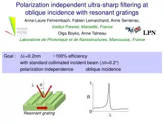
Resonant gratings for narrow band pass filtering applications Olga Boyko, Fabien Lemarchand, Anne Talneau, Anne-Laure Fehrembach and Anne Sentenac Laboratoire de Photonique et Nanostructures, CNRS UPR20, Route de Nozay, 91460 Marcoussis, France Institut Fresnel, CNRS UMR6133, Aix-Marseille universités, D.U. de Saint Jérome, 13397 Marseille, France Ultra narrowband inverse (notch) filters FWHM < 1 nm with polarization independence and good angular tolerance
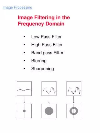
Reflected light R at the resonance R = 1 (and T=0) NOTCH (INVERSE) FILTERS • Subwavelength grating • Dielectric AR structure • Incident plane wave for R = 1 kxoy Incident light Kx z y O x proj. of the incident wavevector evanescent wave kg guided mode Resonance /coupling condition: |kxoy + m Kx| = kg (m integer)
kg kxoy K Different configurations for exciting a guided mode 1. A single guided mode kg is excited with a single evanescent wave under oblique incidence • Resonance very sensitive to the incident angle and the incident polarization • Typically = 5nm for a = 0.2deg Bad performances with standard collimated beam
Different configurations for exciting a guided mode kg kxoy =0 (normal incidence) 2. -K +K A single guided mode kg is excited with the two +/-1 evanescent waves under normal incidence Resonance very sensitive to the incident polarization The angular tolerance may be good with specific grating profiles
Different configurations for exciting a guided mode kg -Kx Kx 3. kx0y A single guided mode kg is twice excited with the two +/-1 evanescent waves under oblique incidence Resonance very sensitive to the incident polarization The angular tolerance may be good with specific grating profiles
Different configurations for exciting a guided mode kg1 kg2 kxOy 4. K -K Two guided modes kg are excited with the two +/-1 evanescent waves under oblique incidence Resonance with a possible good angular tolerance BUT design sensitive to fabrication errors
(x) x 1 (f) 2 f Kx 2Kx 3Kx 4Kx d d1 d1 and d2 d/2 d2 Lamellar grating profiles leading to a good angular tolerance Single mode excitation with single evanescent wave: 1 Guide Mode excitation with two evanescent waves: 1 and 2
kg1 kg +Ky kxOy -Kx +Kx kg2 -Ky • oblique incidence • normal incidence • Combining angular tolerance and polarization independence Angular tolerance: excitation with several evanescent waves and |2| >>|1| Polarization independence: excitation with two orthogonal grating vectors Kx and Ky (2D gratings)
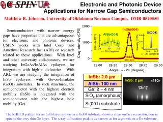
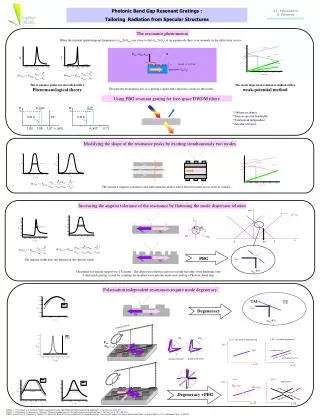
d/4 d/4 365nm 272.5nm 272.5nm 180nm d=940nm SiO2 PMMA Design and fabrication • 4 DIBS layers • electronic lithography (Leica EBPG 5000+)
Experimental characterization set-up reference flux Non polarising polarizing beamsplitter tunable laser 1520-1570nm RGF T photodiode Pigtailed collimator 2w0 = 0.58 mm /2 waveplate R photodiode
A’ B’ theory experience Oblique incidence filter: location of the minima of transmittivity versus and for s and p polarizations A B • experimental and theoretical curves are similar • (same gap width ~ 5nm,opening around 5.8°) • spectral shift: due uncertainty on layer thickness or layer index
Experience Theory (gaussian beam) Points A and A’:polarization independence Gaussian beam: diameter at waist 580µm, full angle divergence 0.2° theoretically Dl=0.2nm (Plane wave: Dl=0.1nm ) experimentally Dl=0.4nm Points B and B’: s and p resonances split and filter performances deteriorated
Conclusion • Few number of layers and subwavelength grating • Specific 2D grating design => polarization independence and good angular tolerance • Experimental demonstration of ultra narrowband inverse filters =0.4nm • Improvement of the maximum R value: larger grating surface (4mm2) and designs with even higher angular tolerance