Download
1 / 13
140 likes | 285 Views
LPN. 1. q. l. R. 0. l. Resonant grating. Polarization independent ultra-sharp filtering at oblique incidence with resonant gratings. Anne-Laure Fehrembach, Fabien Lemarchand, Anne Sentenac, Institut Fresnel, Marseille, France Olga Boyko, Anne Talneau

E N D
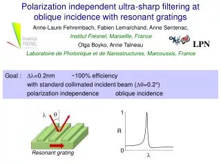
LPN 1 q l R 0 l Resonant grating Polarization independent ultra-sharp filtering at oblique incidence with resonant gratings Anne-Laure Fehrembach, Fabien Lemarchand, Anne Sentenac, Institut Fresnel, Marseille, France Olga Boyko, Anne Talneau Laboratoire de Photonique et de Nanostructures, Marcoussis, France Goal : Dl=0.2nm ~100% efficiency with standard collimated incident beam (Dq=0.2°) polarization independence oblique incidence
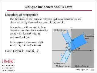
p q 2p/l l s light cone (kp, 2p/lp) kinc kinc kinc z (kp , lp) (-1) E kx y x 0 (kp , lp) ky 2p/l l ~ lp (-1) (-1) 2p/lp d kinc kx kp kp kinc kx K=2p/d - K 0 Resonant grating filters: basic principles • Advantages and limitations: • ultra-narrow bandwidth: Dl < 0.1nm achievable • weak angular tolerance: Dq < 0.05° • strong polarization sensitivity
2p/l 2p/l 2p/l (-1) (-1) (+1) (-1) kinc (-1) (+1) kinc kinc kinc y kx kx kx 0 0 0 z x 2p/l 2p/l (-1) (+1) (-1) (+1) kinc kx 0 kinc TE2 Perturbative model: Dl e1 Dq e2 kx TE1 0 Angular tolerant configuration 2 counter propagative modes, small e1 ,large e2
2p/l e1,-1 s p k symmetry plane p (0,1) symmetric TEp (1,0) kinc s symmetry plane anti - symmetric TEs Polarization independent configuration Symmetry plane, small e1,-1
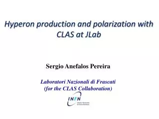
symmetry plane (0,1) (-1,0) (1,0) kinc s (0,-1) p TE2 e1,-1 s p TE1 e1,-1 2p/l 2p/l Dq e2,0 Dl e1,0 • small e1,-1, small e1,0 ,large e2,0 k kx Angular tolerant and polarization independent oblique incidence configuration • Symmetry plane, 2 counter propagative modes Fehrembach, Sentenac, Appl. Phys. Lett., 86, 121105 (2005)
Diameters dB = 347nm dA= 257nm dC= 170nm d/4 d/4 A B d = 890nm A C • design "Doubly periodic patern" • fabrication • layers deposition: • glass substrate / Ta2O5 / SiO2/ Ta2O5 / SiO2 (220nm etched) • electronic lithography etching (component size 1mm2) Design and fabrication • small e1,-1, • small e1,0 , • large e2,0 Scanning electron microscopy picture of the grating
theory experience Minimum of transmittivity versus incident angle and wavelength Results: resonant grating dispersion relation A B A’ B’ • experimental and theoretical dispersion relations are similar • (same gap width ~ 5nm,opening around 5.8°) • Points A and A’: polarization independent, angular tolerant resonance • Points B et B’: weak angular tolerance, polarization sensitivity
q=5.5° q=5.5° Theory q=5.8° Experience q=5.8° diameter at waist 580µm, full angle divergence 0.2° Results: resonant grating spectra Points B and B’: s and p resonances split up, wide bandwidth, low efficiency (Dq=0.02°) Points A and A’:polarization independence, narrow bandwidth, quite good efficiency
Theory, Gaussian beam divergence 0.2° Experience divergence 0.2° Plane wave Dl=0.1nm Dq=0.17° Dl=0.4nm R=100% T=0% R+T=100% R=28% T=52% R+T=80% • Performances deterioration: • Etching imperfections (write fields stitching errors) ? • little diffusion at resonance but 20% energy is lost • Grating finite size effects (1mm²) ? Dl=0.2nm R=65% T=35% R+T=100% Results: experience vs theory
Conclusion • Experimental demonstration of a resonant grating filter with • 0.4nm bandwidth • polarization independence • under 5.8° of incidence • Performances deterioration: weak angular tolerance and finite size effect • Etching in high index, over a wide area • New component: Dl=0.2nm, Dq=0.6°, etched over 3mm²
Transmittivity versus collecting angle, at and outside resonance 1 -15.0 -10.0 -5.0 0.0 5.0 10.0 15.0 Rnorm Hrnorm 0.1 diffusion ? Collecting angle of the detector: 2.7mrad (1mm located at 36cm) transmittivity 0.01 diffusion ? 0.001 Collecting angle (mrad)
Transmittivity and reflectivity with a collecting lens 1 0.9 0.8 0.7 pour info: angle de collection 0.6 200 mrad en T (lentille) R et T 0.5 et 60 mrad en R (cube) 20% of energy at resonance remains lost 0.4 0.3 0.2 0.1 0 1541 1541.5 1542 1542.5 1543 longueur d'onde
Polarisation s+p Incident Réfléchi