Download
1 / 28
310 likes | 533 Views
POWERPC ARCHITECTURE. Term Paper Presentation by Umut Yazkurt CMPE 511 Fall 2003-2004. History. PowerPC is a RISC architecture . It was jointly designed by Apple, IBM, and Motorola by early 1990s .

E N D
POWERPC ARCHITECTURE Term Paper Presentation by Umut Yazkurt CMPE 511 Fall 2003-2004
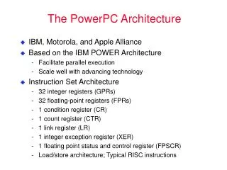
History • PowerPC is aRISC architecture. • It was jointly designed by Apple, IBM, and Motorola by early 1990s. • Aim was to form the basis of a new generation of high-performance low-cost products ranging from low cost embedded controllers to massively parallel supercomputers. • Because of its already largely installed software base, they began with IBM’s POWER architecture which was developed for RS/6000 systems.
History Apple, IBM, and Motorola designed the first four members of the PowerPC microprocessor family simultaneously. • PowerPC 601™ : the first 32 bit implementation of the PowerPC architecture providing medium levels of performance for desktop computers and workstations. • PowerPC 603™ :a 32-bit low-power processor primarily for cost-sensitive desktop and portable personal computer systems. • PowerPC 604™ : 32-bit implementations of the PowerPC architecture designed for use in high performance desktop, workstation, and symmetric multiprocessing computer systems. • PowerPC 620™ : 64-bit implementation of the PowerPC architecture providing high levels of performance for technical and scientific workstations, application and LAN servers and symmetric multiprocessing computer systems.
General • The PowerPC architecture specifies an instruction set architecture (ISA). • It is independent of implementation aspects. • It allows anyone to design and fabricate compatible PowerPC processors independent of implementation differences as the technology advances.
General • All PowerPC processors run the same core PowerPC instruction set. • They differ primarily in the degree of dedicated hardware support for multiple execution units, cache size and capability, length of pipeline, and interface busses. • These differences result in different tradeoffs in processing performance, die area, and power dissipation.
Programming Model • The PowerPC architecture is a full 64-bit architecture with full 64-bit integers and 64-bit logical address pointers. • It also has a well defined 32-bit subset. Designers may implement either 32- or 64-bit machines. To enable 32-bit applications to run on all PowerPC processors, 64 bit machines are required to support a 32-bit operating mode. • The 32-bit processors have 32-bit wide general registers and branch-address registers; 64 bit processors have 64-bit wide registers.
Programming Model • Instructions always operate on machine’s full register width: 32 or 64 bits. • Instructions are mode independent ; a given instruction operates the same on 32-bit machines , 64-bit machines, and 64-bit machines operating in 32-bit mode. • A 64-bit machine operating in 32-bit mode passes only the low-order 32 bits of an address to the address translation mechanism, and the ALU calculates carry and over-flow based on a 32-bit result.
Logical Address Space • For 32-bit machines and 64-bit machines operating in the 32-bit mode, the linear array of bytes that can be addressed by a pointer is 4 gigabytes. • For 64-bit machines operating in 64-bit mode, 18 terabytes of memory can be addressed.
Initialization • When the processor is first initialized, it is in supervisor (also called privileged) mode. In this mode, all processor resources, including registers and instructions are accessible. • The processor can limit access to certain privileged registers and instructions by placing itself in user mode. • This protection limits application code from being able to modify global and sensitive resources, such as the caches, memory management system, and timers.
Registers Architecture defines five types of registers : • Special Purpose Registers (SPRs) • General Purpose Registers (GPRs) • Floating Point Registers (FPRs) • Device Control Registers (DCRs) • Machine State Register (MSR)
Registers • SPRs give status and control of resources within the processor core.
Registers Five important user mode SPRs are: • The Fixed-Point Exception Register (XER) is used for indicating conditions for integer operations, such as carries and overflows. • The Floating-Point Status and Control Register (FPSCR) is a 32-bit register used to store the status and control of the floating-point operations. • The Count Register (CTR) is used to hold a loop count that can be decremented during the execution of branch instructions. • The Condition Register (CR) is a 32-bit register grouped into eight fields, where each field is 4 bits that signify the result of an instruction’s operation: Equal (EQ), Greater Than (GT), Less Than (LT), and Summary Overflow (SO). • The Link Register (LR) contains the address to return to at the end of a function call.
Registers General Purpose Registers : • The Architecture specifies that all implementations have 32 GPRs (GPR0 - GPR31). • GPRs are the source and destination of all fixed-point operations and load/store operations. They also provide access to SPRs and DCRs. • They are all available for use in every instruction with one exception: In certain instructions, GPR0 simply means “0” and no lookup is done for GPR0’s contents.
Registers Floating Point Registers : • The PowerPC architecture provides thirty-two 64-bit floating-point registers. Device Control Registers : • DCRs are similar to SPRs in that they give status and control information, but DCRs are for resources outside the processor core. • DCRs allow for memory-mapped I/O control without using up portions of the memory address space.
Registers Machine State Register : • MSR represents the state of the machine. • It is accessed only in supervisor mode, and contains the settings for things such as memory translation, cache settings, interrupt enables, user/privileged state, and floating point availability. Exact control bits vary by implementation. • The MSR does not readily fit into the SPR/DCR/GPR classification, as it contains its own pair of instructions to read and write the contents of the MSR into a GPR.
Data Types • PowerPC can deal with data types of 8–bits (byte), 16-bits (halfword), 32-bits (word) and 64-bits (doubleword) in length. It can use either little-endian or big-endian style; that is, the least significant byte is stored in the lowest or highest address. • Fixed-point data types include: * Unsigned byte * Unsigned halfword * Signed halfword * Unsigned word * Signed word * Unsigned doubleword * Byte Strings: From 0 – 128 bytes in length • Floating-point data types include IEEE-754 single- and double-precision types.
Instruction Format • The architecture encodes all instructions in 32 bits and aligns them on word address boundaries in memory. • Instructions are first decoded by the upper 6 bits, in a field called the primary opcode. The remaining 26 bits contain operands and/or reserved fields. • Different types of instructions defined are : ALU, Floating Point , Load/Store, Branch, Condition and Synchronization Instructions
Addressing Modes Three types of operand addressing : • Memory operand addressing: • Indirect addressing : * Base address in a GPR + a 16-bit sign-extended literal • Indirect-indexed addressing : * Base address in a GPR + displacement from another GPR • ALU and Floating-point instruction operandaddressing: • Three-register Format • Branch Operand Addressing : • Absolute : Use the literal as the absolute address. • Relative : Use the literal as the displacement from the branch instruction address. • Indirect : Take the target address from the LR or CTR registers
PowerPC G4e Pipelining • Seven Stage Pipeline • Superscalar Microprocessor – allows multiple instructions to be executed in parallel. Nine Execution Units • BPU : Branch Processing Unit • VPU : Vector Permute Unit • VIU : Vector Integer Unit • VCIU : Vector Complex Integer Unit • VFPU : Vector Floating Point Unit • FPU : Floating Point Unit • IU : Integer Unit • CIU : Complex Integer Unit • LSU : Load/Store Unit
G4e’s microarchitecture with emphasis on pipeline stages of the front end and the functional units.
PowerPC G4e Pipeline Stages • Stages 1 and 2 - Instruction Fetch: • These two stages are both dedicated primarily to grabbing an instruction from the L1 cache. • The G4e can fetch four instructions per clock cycle from the L1 cache and send them on to the next stage • Stage 3 - Decode/Dispatch: • Once an instruction has been fetched, it goes into a 12-entry instruction queue to be decoded. • The G4e's decoder can dispatch up to three instructions per clock cycle to the next stage.
PowerPC G4e Pipeline Stages • Stage 4 - Issue: • The first queue Floating-Point Issue Queue (FIQ), which holds floating-point (FP) instructions that are waiting to be executed. • The second is the Vector Issue Queue (VIQ), which holds vector operations. • The third queue is the General Instruction Queue (GIQ), which holds everything else. • Once the instruction leaves its issue queue, it goes to the execution engine to be executed.
PowerPC G4e Pipeline Stages • Stage 5 - Execute: • The instructions can pass out-of-order from their issue queues into their respective functional units and be executed. • Stage 6 and 7 - Complete and Write-Back : • In these two stages, the instructions are put back into the order in which they came into the processor, and their results are written back to memory.