Signal Resolution and Data Flow Models
530 likes | 719 Views
Signal Resolution and Data Flow Models. Dr. Alaaeldin Amin. Signal Resolution Function. Each Signal Assignment Statement Defines a Signal Driver ( Source ) Example : S <= a After T ;

Signal Resolution and Data Flow Models
E N D
Presentation Transcript
Signal Resolution andData Flow Models Dr. Alaaeldin Amin
Signal Resolution Function • Each Signal Assignment Statement Defines a Signal Driver (Source) Example: S<=aAfter T ; • Multiple Concurrent Assignment Statements To The Same Signal Defines Multiple Drivers (Signal Sources). • Such Multi-Driver Signals Are Commonly Encountered in Buses with Multiple Drivers • Electrically, Tri-State or Open-Collector Drivers Are Used to ResolveConflicts of the Different Drivers • VHDL Model Requires the Definition of a Resolution FunctionTo Resolve Values Being Assigned to the Common Signal By All Its Drivers
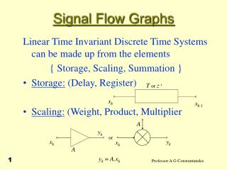
DATA FLOW MODEL • Represents Register Transfer operations • There is Direct Mapping between Data Flow Statements && Register Structural Model • Implied Module Connectivity • Implied Muxes & Buses Main Data Flow VHDL Constructs: • Concurrent Signal Assignment Statements • Block Statement
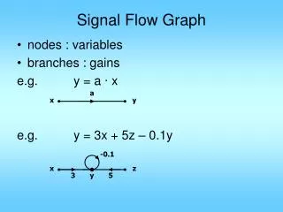
Conditional Signal Assignment [ Label: ] target <= [Guarded] [Transport ] Wave1 when Cond1 Else Wave2 when Cond2 Else …………………………….. Waven-1 when Condn-1 Else Waven ; -- Mandatory Wave Optional Selected Signal Assignment [Label:] WithExpression Select target <= [Guarded] [Transport] Wave1 when Choice1 , Wave2 when Choice2 , …………………………… Waven-1 when Choicen-1 , Waven when OTHERS; Concurrent Signal Assignment: UnconditionalBoth Sequential & Concurrent ConditionalOnly Concurrent Conditions Must Be Boolean, May Overlap and Need Not Be Exhaustive SelectedOnly Concurrent Cases Must Not Overlap and Must Be Exhaustive) VHDL-93 Any WaveiCan Be Replaced By the Keyword UNAFFECTED (Which Doesn’t Schedule Any Transactions on the Target Signal.)
Examples Ex A 2x4 Decoder Signal D : Bit_Vector(1 To 4) := “0000”; Signal S0, S1 : Bit; ………………………………………… Decoder: S <= “0001” after T When S1=‘0’ and S0=‘0’ else “0010” after T When S1=‘0’ else “0100” after T When S0=‘0’ else “1000” ; Ex 4-Phase Clock Generator Signal Phi4 : Bit_Vector(1 To 4) := “0000”; ………………………………………… ClkGen: With Phi4 Select Phi4 <= “1000” after T When “0000” , Phi4 <= “0100” after T When “1000” , Phi4 <= “0010” after T When “0100” , Phi4 <= “0001” after T When “0010” , Phi4 <= “1000” after T When “0001” , Phi4 <= “0000” WhenOthers; -- Exhaustive
Block Statement • Block Statement is a Concurrent VHDL Construct Which is Used Within an Architectural Body to Group (Bind) a Set of Concurrent Statements. Required Optional Block_Label: Block(Guard_Condition) Block_Declarations; Begin Concurrent_Statements; END Block Block_Label ; • A Guard Condition May be Associated with a Block Statement to Allow Enabling/Disabling of Certain Signal Assignment Statements. • The Guard Condition Defines an Implicit Signal Called GUARD. • In the Simplest Case, Binding (Packing !) Statements Within A Block Has No Effect On the Model. • Blocks Can Be Nested. Optional
Guard Condition Block Local Signal Example : Architecture DF of D_Latch is Begin B : Block (Clk = `1`) Signal I_State :Bit; Begin I_State <=Guarded D ; Q <= I_State after 5 ns; QB <=not I_State after 5 ns; END Block B ; END DF ; Notes • If Guard Condition (Clk=`1`) is TRUE, Guarded Statements within block are Enabled (Made Active) • Guarded Statements (e.g., I_State) execute when • Guard Condition Becomes True, AND • While Guard Condition is True, a Signal on the RHS Changes Value • UnGuarded Signal Targets (e.g., Q, QB) are independent of the Guard Condition
Works Fine Examples +ive Edge-Triggered D-FF LibraryIEEE; Use IEEE.Std_Logic_1164.ALL; Entity DFF is Generic(TDel: Time:= 5 NS); Port(D, Clk: Std_Logic; Q, QB: outStd_Logic); End DFF; Arch 1 Architecture DF1_NO_Block of DFF is Signal I_State: Std_Logic:='1'; begin I_State <= D when (Clk='1' and Clk'Event) else I_state; Q <= I_state after TDel ; QB <= not I_state after TDel ; End DF1_NO_Block ;
Doesn’t Work Works Fine Examples Arch 2 Architecture DF2_NO_Block of DFF is Signal I_State: Std_Logic:='1'; begin I_State <= D after TDelwhen (Clk='1' and (not(Clk'Stable))) else I_state; Q <= I_state; QB <= not I_state; End DF2_NO_Block ; Arch 3 Architecture DF3_NO_Block of DFF is Signal I_State: Std_Logic:='1'; begin I_State <= D when (Clk='1' and (not(Clk'Stable))) else I_state; Q <= I_state after TDel; QB <= not I_state after TDel; End DF3_NO_Block ;
Doesn’t Work Works Fine Examples Arch4 Architecture DF1_Block of DFF is Signal I_State: Std_Logic:='1'; begin D_Blk: Block(Clk='1' and Clk'Event) Begin Q <= GuardedD after Tdel; QB <= Guardednot D after Tdel; End Block; End DF1_Block ; Arch5 Architecture DF2_Block of DFF is Signal I_State: Std_Logic:='1'; begin D_Blk: Block(Clk='1' and not Clk'Stable) Begin Q <= GuardedD after Tdel; QB <= Guardednot D after Tdel; End Block; End DF2_Block ;
Clk='1' and Clk'Event CLK Signal Evaluated here (Clk='1' and Clk'Event) = FALSE Signal Evaluated here (Clk='1' and Clk'Event) = TRUE Examples Arch 1 Architecture DF1_NO_Block of DFF is Signal I_State: Std_Logic:='1'; begin I_State <= D when (Clk='1' and Clk'Event) else I_state; Q <= I_state after TDel; QB <= not I_state after TDel; End DF1_NO_Block ; Signal Evaluated 2-Times Per Clock Cycle
Doesn’t Work Clk='1' and Clk'Event CLK Clk‘Stable d d Signal Evaluated here (Clk='1' and not Clk‘Stable)= FALSE Signal Evaluated here (Clk='1' and not Clk‘Stable)= TRUE Signal Evaluated 4-Times Per Clock Cycle Examples Arch 2 Architecture DF2_NO_Block of DFF is Signal I_State: Std_Logic:='1'; begin I_State <= D after TDelwhen (Clk='1' and (not(Clk'Stable))) else I_state; Q <= I_state; QB <= not I_state; End DF2_NO_Block ;
Works Fine Clk='1' and Clk'Event CLK Clk‘Stable d d Signal Evaluated here (Clk='1' and not Clk‘Stable)= FALSE Signal Evaluated here (Clk='1' and not Clk‘Stable)= TRUE Signal Evaluated 4-Times Per Clock Cycle Examples Arch 3 Architecture DF3_NO_Block of DFF is Signal I_State: Std_Logic:='1'; begin I_State <= D when (Clk='1' and (not(Clk'Stable))) else I_state; Q <= I_state after TDel; QB <= not I_state after TDel; End DF3_NO_Block ;
Doesn’t Work Examples Arch4 Architecture DF1_Block of DFF is Signal I_State: Std_Logic:='1'; begin D_Blk: Block(Clk='1' and Clk'Event) Begin Q <= GuardedD after Tdel; QB <= Guardednot D after Tdel; End Block; End DF1_Block ; GUARD <= Clk='1' and Clk'Event FALSE TRUE Signal Evaluated Continuously while Clk = ‘1’ !!!
Works Fine GUARD <= Clk='1' and not Clk‘Stable TRUE FALSE d Examples Arch5 Architecture DF2_Block of DFF is Signal I_State: Std_Logic:='1'; begin D_Blk: Block(Clk='1' and not Clk'Stable) Begin Q <= GuardedD after Tdel; QB <= Guardednot D after Tdel; End Block; End DF2_Block ; Signal Evaluated Once Per Clock Cycle (At Rising Edge of the Clock)
example ``Nested Blocks`` Architecture Block_Structure of Demo is begin A: Block -- 1 Outer Block Declarative Section; Begin Concurrent Statements of Outer Block; B:Block -- 1.1 Inner Block ``A`` Declarative Section; begin Concurrent Statements of Inner Block ``A``; .................................. end Block B; C:Block -- 1.2 Inner Block ``B`` Declarative Section; begin Concurrent Statements of Inner Block ``B``; .................................. end Block C; end Block A; D: Block -- 2 .................................. end Block D; endBlock_Structure;
Use of Nested Blocks For Composite Enabling Conditions • ARCHITECTURE guarding OF DFF IS • BEGIN • edge: BLOCK ( c = '1' AND NOT c'STABLE ) • BEGIN • gate: BLOCK ( e = '1' ANDGUARD ) • BEGIN • q <= GUARDED d AFTER delay1; • qb <= GUARDED NOT d AFTER delay2; • END BLOCK gate; • END BLOCK edge; • END guarding; • Inner Guard Signal <= (e= '1') AND ( c= '1' AND NOT c'STABLE) • Can nest block statements • Combining guard expressions must be done explicitly • Implicit GUARD signals in each block
EXAMPLE • Model A System with 2 8-Bit Registers R1 and R2, a 2-Bit Command signal “COM” and an external 8-Bit Input “INP” • When Com= “00” R1 is Loaded with External Input • When Com= “01” R2 is Loaded with External Input • When Com= “10” R1 is Loaded with R1+R2 • When Com= “11” R1 is Loaded with R1-R2 Use Work.Utils_Pkg.ALL Entity DF_Ex is Port (Clk: Bit; Com: Bit_Vector (1 DownTo 0); Input: Bitvector(7 DownTo 0)); End DF_Ex; -- Architecture DF of DF_Ex is Signal Mux_R1, R1, R2, R2C, R2TC, Mux_Add, Sum: Bit_Vector(7 DownTo 0); Signal D00, D01, D10, D11, LD_R1: Bit; Begin D00 <= not Com(0) andnot Com(1); -- Decoder D01 <= not Com(0) and Com(1); -- Decoder D10 <= Com(0) andnot Com(1); -- Decoder D11 <= Com(0) and Com(1); -- Decoder - -
EXAMPLE R2C <= not R2; R2TC <= INC(R2C); -- Increment Function Defined -- in the Package Mux_Add <=R2TCwhen D11 = ‘1’ Else R2 ; Sum <= ADD(R1, Mux_Add); -- ADD Function -- Defined in Package Mux_R1 <= INPwhen D00 = ‘1’ Else Sum; R1E <= D00 OR D10 OR D11; Rising Edge: BLOCK(Clk=‘1’ and not Clk’Stable) R1_Reg: BLOCK(R1E=‘1’ ANDGUARD) R1 <= Guarded Mux_R1 ; End Block R1_Reg ; R2_Reg: BLOCK(D01=‘1’ ANDGUARD) R1 <= Guarded INP; End Block R2_Reg ; End BlockRising Edge;
RHS Guard T1 T2 …. T3 0 V1 V2 …. V3 Driving Value Projected Waveform Resolution of Guarded Signals • (GUARD = False) LHS Signal is Disconnected from its Driver Signals on the RHS • No New Transactions May Be Placed on the LHS Signal Driver • Pending Transactions on the PWFM of the Signal Continue to Affect the Signal Value as they Expire.
T3 T1 …. T2 T2 …. T1 T3 0 0 V3 …. V1 V2 …. V1 V3 V2 Driver 1 Driving Value RF Driver n Resolution of Guarded Signals • Resolved Non-Guarded LHS Signal Values Are Determined by The Resolution Function from CVs of all Driver Signals on the RHS • Expired Transactions on Any of the Signal Drivers, Activates the RF to Determine the new value of the output signal • Pending Transactions on the PWFM of the Signal Continue to Affect the Signal Value (Through RF) as they Expire.
RHS RHS Guard Guard …. T2 T1 T3 T1 …. T2 T3 0 0 V3 …. V2 V1 V2 V1 …. V3 Driver 1 Driving Value RF Driver n Resolution of Guarded Signals • Only Drivers with (GUARD = True)Participate in Determining Value of Target Signal • If a Driver has (GUARD = False) It is Considered Turned-Off • A Resolved Guarded Signal is Declared to Be of either REGISTERkindor BUS Kind. • Register Signals drivers DO NOT Invoke the RF in Case All Drivers Are Turned Off Signal Retains its Previous Value. • Signals of BUS Kind Invoke the RF is in case All Signal Drivers Are Turned Off RF is Invoked with a NULL input Default Value is Returned.
RHS Guard Expression T1 T2 …. T3 0 V1 V2 …. V3 Driving Value RF Projected Waveform Resolution of Guarded Signals • Events and Transactions on Signals of BUS & Register Kind are Exactly the Same as long as at least One Driver is ON • When All Drivers Are OFF, Register Signals will Maintain Their Previous Values while BUS Signals will Assume the Default Value of the RF.
Syntax Signal<sig_name> :<resolvedsig_subtype> [kind] [:=Initial_Value] ; Signal_kind ::= BUS | Register Examples: Signal x : Wired_MVL4 BUS ; Signal y : Wired_MVL4 Register ; Note: 1. Only Signals of KindBUS May be Specified for as Port Signals 2. Signals of Register Kind May NOT be Specified as Port Signals) Example Entity ex is Port(s1, s2 : in MVL4; Z: out wired_MVL4 BUS) ; End ex;
Example MOS (PTL) Multiplexer FUNCTION wire (a, b : qit) RETURN qit IS CONSTANT qit_and_table : qit_2d := ( ('0','X','0','X'), ('X','1','1','X'), ('0','1','Z','X'), ('X','X','X','X')); BEGIN RETURNqit_and_table (a, b); END wire;
Example MOS (PTL) Multiplexer FUNCTIONwiring ( drivers : qit_vector) Return qit IS Variable accumulate : qit := 'Z'; -- Default BEGIN FOR i IN drivers'RANGE LOOP accumulate := wire (accumulate, drivers(i)); END LOOP; RETURN accumulate; END wiring; SUBTYPEwired_qit IS wiring qit; TYPE wired_qit_vector IS Array (Natural Range <>) OF wired_qit;
Example MOS (PTL) MultiplexerModel 1 (BUS Signal Kind) USE WORK.basic_utilities.ALL; -- FROM PACKAGE USE: wired_qit Architecture multiple_guarded_assignments OF mux_8_to_1 IS SIGNAL t : Wired_qitBUS; BEGIN b7: Block (s7 = '1' OR s7 = 'Z') Begin t <= Guarded i7; End Block; b6: Block (s6 = '1' OR s6 = 'Z') Begin t <= Guarded i6; End Block ; b5: Block (s5 = '1' OR s5 = 'Z') Begin t <= Guarded i5; End Block ; b4: Block (s4 = '1' OR s4 = 'Z') Begin t <= Guarded i4; End Block ; b3: Block (s3 = '1' OR s3 = 'Z') Begin t <= Guarded i3; End Block ; b2: Block (s2 = '1' OR s2 = 'Z') Begin t <= Guarded i2; End Block ; b1: Block (s1 = '1' OR s1 = 'Z') Begin t <= Guarded i1; End Block ; b0: Block (s0 = '1' OR s0 = 'Z') Begin t <= Guarded i0; End Block ; -- z <= not t after 1 NS; END multiple_guarded_assignments; • Disconnection is realized by block statements • If all drivers are disconnected • Hardware returns to 'Z’ Modeling This Requires Using BUS Signal Kind.
Example MOS (PTL) MultiplexerModel 2 (Register Signal Kind) • USE WORK.basic_utilities.ALL; • -- FROM PACKAGE USE: wired_qit • Architecture multiple_guarded_assignments OF mux_8_to_1 IS • SIGNAL t : Wired_qitREGISTER; • BEGIN • b7: Block (s7 = '1' OR s7 = 'Z') Begin t <= Guarded i7; End Block; • b6: Block (s6 = '1' OR s6 = 'Z') Begin t <= Guarded i6; End Block ; • b5: Block (s5 = '1' OR s5 = 'Z') Begin t <= Guarded i5; End Block ; • b4: Block (s4 = '1' OR s4 = 'Z') Begin t <= Guarded i4; End Block ; • b3: Block (s3 = '1' OR s3 = 'Z') Begin t <= Guarded i3; End Block ; • b2: Block (s2 = '1' OR s2 = 'Z') Begin t <= Guarded i2; End Block ; • b1: Block (s1 = '1' OR s1 = 'Z') Begin t <= Guarded i1; End Block ; • b0: Block (s0 = '1' OR s0 = 'Z') Begin t <= Guarded i0; End Block ; • -- • z <= not t after 1 NS; • END multiple_guarded_assignments; • Disconnection is realized by block statements • If all drivers are disconnected Real hardware Maintains State for few milliseconds (As Charge on the Capacitance of Node “t”. • Use Register to implement this behavior
Z X F2 PS F1 Register D Guard Signal Mealy Machine ExampleUsing Block Statements entity Mealy_Mc is Port(Clk, X: in Bit; Z : out Bit); end Mealy_Mc; Architecture Mealy_Blockof Mealy_Mc is Type Stateis (St0, St1, St2); Type St_Vector is array (Natural range <>) of State ; Function State_RF(Signal X: St_Vector ) Return Stateis Begin Return X(X`Left); End State_RF ; Signal PS: State_RFStateREGISTER := St0; Begin B1: Block(notClk`STABLEandClk = `1`) begin S0:Block((PS = St0) and Guard) begin PS <= GuardedSt1 when X=`0` else St2; end block S0;
S1:Block((PS = St1) and Guard) begin PS <= GuardedSt2 when X=`0` else St0; end block S1; S2:Block((PS = St2) and Guard) begin PS <= GuardedSt1 when X=`1` else St2; end block S2; End Block B1; Z <= `1` whenPS =St1 and X=`0` else `0` whenPS =St1 and X=`1` else `0` whenPS =St2 and X=`0` else `1` whenPS =St2 and X=`1` else `0` ; End Mealy_Block; Notes: • Since there are 3 concurrent Signal assignments to the Signal PS , it is declared as a Resolved Signal with the RF being ``State_RF``.
Signal PS is also declared to be of REGISTERkind. This Means that the Signal is Guarded and Resolved and that the RF is not Invoked in Case All its Drivers Are Turned Off (e.g. when CLK = ‘0’) in which case the Signal Retains its Previous Value. • The Outer Block Statement ``B1`` Defines an IMPLICITGuardSignal Which is TRUE only On the Rising Edge of the Clock. • The Implicit Guard Signal ANDed with the Present State Define the Guard Condition for the Nested Block Statements. • ONE Inner Block Statement is Assigned to Each Possible Present State • The State Machine Model Used Allows only One Driver of the Resolved Signal PS to be Active at any Given Time. Thus the `Left Attribute is Used in the RF to Derive the Signal Value Forced By this Driver.
Initial / Reset State Sequence Detector Example Overlapped Detection of the Sequence “1011” • A simple 1011 Mealy Sequence Detector • Single Input x and A single Output z • For x= 011011011011110111 • z= 000001001001000010 Entity detector IS PORT (x, clk : IN Bit; z : out Bit); END detector;
Architecture Singular_state_machine OF Detector IS TYPE State IS (Reset, Got1, Got10, Got101); Type State_vector Is Array (Natural Range <>) Of State; FunctionOne_of (Sources : State_vector) Return State Is BEGIN RETURN Sources(Sources’Left); End One_of; Signal PS : One_of State Register := Reset; Begin Clocking : BLOCK (Clk = '1' AND NOT Clk‘Stable) Begin S1: BLOCK ( PS = Reset AND GUARD ) BEGIN PS <= GUARDED Got1 When X = '1' Else Reset; End Block S1; S2: Block ( PS = Got1 And Guard ) Begin PS <= GUARDED Got10 When X = '0' Else Got1; End Block S2; S3: Block ( PS = Got10 And Guard ) Begin PS <= Guarded Got101 When X = '1' Else Reset; End Block S3;
S4: Block ( PS = Got101 And Guard) • Begin • PS <= Guarded Got1 When X = '1' Else Got10; • End Block S4; • End Block Clocking; • -- • Z <= '1' When ( PS = Got101 And X = '1') Else '0'; • -- • End Singular_state_machine; • PS receives four concurrent assignments • PS must be resolved; use one_of as an RF
Multiplier Design Start S0 Start AR A BR B PR0 AR = 0 S1 AR > 0 • Design a Multiplier Circuit Which Multiplies 2 Unsigned n-Bit Numbers A (multiplicand) & B (multiplier). • The Product (P) is Evaluated by Repeated Additions of the Multiplicand (B) to itself a Number of Times Equals the Multiplier (A) Value. • Example • 1. A=3, B=4 P = 4 + 4 +4 • 2. A=0, B=4 P = 0 • 3. A=3, B=0 P = 0 + 0 + 0 • Required Data Path Modules: • A-Register (n-Bits) AR • B-Register (n-Bits) BR • P-Register (2n-Bits) PR • Adder
Controller Model Architecture DF of CPath_Mult is Type States is (Initial, Iterative); Type State_Vector is Array (Natural Range <>) of States; FunctionRF(V:State_Vector) Return States is Begin Return V(V'Left); end RF; --________________________________________________ Signal PS: RF States Register := Initial; Begin edge: Block(Clk='1' and not Clk'Stable) Begin S0: Block(PS= Initial and Guard) Begin PS <= Guarded Iterative when Start='1' Else Initial; end Block S0;
S1: Block(PS= Iterative and Guard) Begin PS <= Guarded Iterative when Zero /='1' Else Initial; end Block S1; -- -------------- LD_AR <= '1' when PS= Initial and Start='1' else '0'; LD_BR <= '1' when PS= Initial and Start='1' else '0'; Clr_PR <= '1' when PS= Initial and Start='1' else '0'; LD_PR <= '1' when PS=Iterative and Zero /= '1' else '0'; DEC_AR <= '1' when PS=Iterative and Zero /= '1' else '0'; End Block edge; End DF;
Data Path Model Entity DPath_Mult is Generic(N: Positive:= 8); Port(LD_AR, LD_BR, CLR_PR, LD_PR,Dec_AR, Clk: Bit ; A, B: in Bit_Vector(N-1 DownTo 0); Zero: out Bit :='0'; P: out Bit _Vector(2*N-1 DownTo 0)); End DPath_Mult ; -- --------------------- Architecture DF of DPath_Mult is Signal AR, BR : Bit _Vector(N-1 DownTo 0); Signal PR : Bit _Vector(2*N-1 DownTo 0); Signal ARE,BRE,PRE : Boolean:=False ; -- -------------------- Begin ARE <= LD_AR='1' or DEC_AR='1' ; BRE <= LD_BR='1' ; -- Inner Block (Register) Enable Signals PRE <= LD_PR='1' or CLR_PR='1' ; --
Data Path Model edge: Block(Clk='1' and not Clk'Stable) Begin AReg: Block(ARE and Guard) Begin AR <= GuardedAwhen LD_AR='1' ElseInt2Bin(Int_Val(AR)-1 , AR'Length)when Int_Val(AR)> 0 else Unaffected; Zero <= '1' when (Int_Val(AR)=0) else '0'; end Block AReg; BReg: Block(BRE and Guard) Begin BR <= Guarded B; end Block BReg; PReg: Block(PRE and Guard) Begin PR <= GuardedInt2Bin((Int_Val(PR)+ Int_Val(BR)), PR'Length) when LD_PR='1' ElseInt2Bin(0, 2*N); end Block PReg; End Block edge; P <= PR ; End DF;
Disconnection of BUS Signals • Guarded Resolved Signal assignment can specify disconnection delay. The DISCONNECTION statement is placed in the declarative part of the Architecture and applies to all assignments to this signal. Architecture DF of Ex is EXAMPLE Architecture DF of Example is Signal X : WX_Vector(7 downTo 0) BUS; DISCONNECTX : WX_Vector after50 ns; Begin B1: Block(Ph1=`1`) Signal P1_S :WX_Vector(7 downTo 0) ; Begin P1_S <= …. X<=GuardedP1_S after 75 ns; End Block B1; B2: Block(Ph2=`1`) Signal P2_S :WX_Vector(7 downTo 0) ; Begin P2_S <= …. X<=GuardedP2_S after 60 ns; End Block B2; END DF ;
Example“Register Signals”+ive Edge-Triggered Shift Register with Parallel Load • Register INPUTS In Order of Priority • Ena : If Ena=0, The register Cannot not Change its state. • LD : IF LD = 1, Data on the parallel inputs (Din) are Loaded into the Register independent of the Clock Signal (Asynchronous Load) • Dir : Determines the Direction of the Shift or Rotate Operation. Dir=0 indicates a Left shift/Rotate while Dir = 1, indicates a Right Shift /Rotate. • Shift Mode Signals M1 & M2 • M1M2 : 00 A 0 is Shifted-In • M1M2 : 01 A 1 is Shifted-In • M1M2 : 10 The Sin input is Shifted-In • M1M2 : 11 Rotate Operation.
RF Function Example Type MVL4 is (‘X’, ‘0’, ‘1’, ‘Z’); Type MVL4_Vec is Array(Natural range <>) of MVL4 ; Type MVL4_Tab is array(MVL4 , MVL4) of MVL4; Constant Tab_X : MVL4_Tab := -- 'x', '0', '1', 'Z' ------------------------ (('x', 'x', 'x', 'x'), -- 'x' ('x', '0', 'x', '0'), -- '0' ('x', 'x', '1', '1'), -- '1' ('x', '0', '1', 'z')); -- 'z' FunctionWiredX (INP : MVL4_Vec) Return MVL4 is Variable Result: MVL4:='z';--Initialize Begin For i in INP'Range Loop Result:= TAB_X(Result , INP(i)); End Loop; Return Result; endWiredX; SubType WX is WiredX MVL4 ; Type WX_Vector is Array(Natural range <>) of WX ;
Entity ShiftReg is Port ( Ena, Ld, Clk, Dir, M1, M2 : in Bit; Sin : in MVL4 ; Din : in WX_Vector(7 downto 0); Q : Out WX_Vector(7 downto 0)); END ShiftReg ; Architecture Wrong_DF of ShiftReg is Signal I_State : WX_Vector(7 downto 0); Begin Load: Block(Ena=‘1’ and Ld=‘1’) begin I_State <= Guarded Din; end block Load; Shift: Block(Ena=‘1’ and Ld=‘0’ and Clk=‘1’ and not Clk`Stable)) begin With Dir & M1 & M2 Select I_State <= Guarded I_State(6 downto 0) & ‘0’ When “000” , I_State(6 downto 0) & ‘1’When “001” , I_State(6 downto 0) & Sin When “010” , I_State(6 downto 0) & I_State(7) When “011” , ‘0’ & I_State(7 downto 1) When “100” , ‘1’ & I_State(7 downto 1) When “101” , Sin & I_State(7 downto 1) When “110” , I_State(0)& I_State(7 downto 1) When “111”; end block Shift; Q <= I_State After 5 ns ; EndWrong_DF;
Architecture Correct_DF of ShiftReg is Signal I_State : WX_Vector(7 downto 0) Register; Begin Load: Block(Ena=‘1’ and Ld=‘1’) begin I_State <= Guarded Din; end block Load; Shift: Block(Ena=‘1’ and Ld=‘0’ and Clk=‘1’ and not Clk`Stable)) begin With Dir & M1 & M2 Select I_State <= Guarded I_State(6 downto 0) & ‘0’ When “000” , I_State(6 downto 0) & ‘1’When “001” , I_State(6 downto 0) & Sin When “010” , I_State(6 downto 0) & I_State(7) When “011” , ‘0’ & I_State(7 downto 1) When “100” , ‘1’ & I_State(7 downto 1) When “101” , Sin & I_State(7 downto 1) When “110” , I_State(0)& I_State(7 downto 1) When “111”; end block Shift; Q <= I_State After 5 ns ; EndCorrect _DF;