INTEGRATED CIRCUITS
INTEGRATED CIRCUITS. Dr. Esam Yosry. Lec . #8. Introduction Resistor Design Capacitor Design Inductor Design MOSFETs (CMOS) BJTs BiCMOS. VLSI Components in CMOS Technology. Introduction ( Chip Fabrication Cycle). Resistor Design.


INTEGRATED CIRCUITS
E N D
Presentation Transcript
INTEGRATED CIRCUITS Dr. EsamYosry Lec. #8
Introduction • Resistor Design • Capacitor Design • Inductor Design • MOSFETs (CMOS) • BJTs • BiCMOS VLSI Components in CMOS Technology
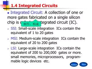
Resistor Design • Assume we have a sheet of material of thicknesst and widthW, then A = W t • Next assume that L = W; which means that we have a square, then the resistance becomes the sheet resistance per square (Ω/□). Material technological parameters
Resistor Design • The fabrication house supplies the designer with the values of the sheet resistance R□. • R□ resistance of one square of the fabricated silicon layer. • The engineer designs for the number of squares to be put in series or in parallel to get the needed resistance.
Resistor Design R • Sheet Resistance • Counting Squares • End Contacts • Bends (Corners) 3R R/3 2dx2d Corner = 0.65 End contact = 0.3 to 0.4 (0.35 is typical) CC=dxd
Resistor Design • Example • If R□= 100 Ω/□,and the resistance needed is 200 Ω, then two squares are added in series. • If the resistance needed is 50 Ω, then two squares must be put in parallel. • n squares in series R= n R□ • n squares in parallel R= R□/n • The sheet resistance of the diffused layer from 10 to 200Ω(100kΩ?!)
2dx2d CC=dxd Equivalent Resistance of End Contacts • R= body resistance (nR) + end contacts resistance (2x0.35R) + corners resistance (ncx0.65R) + metal/Si contact resistance RC (usually very low) End contact = 0.35
Resistor’s Accuracy • Absolute Accuracy • Matching Accuracy *Resistors are usually made from polysilicon * Inaccuracy comes from poly line edge-shift during processing (PR dimensional change, lateral etching, UV diffraction,…etc) *As inaccuracy is almost the same in the two resistors matching accuracy is very high
n squares Absolute Accuracy • Rnominal = n R =(nL/L) R = (length/width) R • Include line-edge shift of L R = (length L / L L) R (length /L L) R = (length/L)(1+ L/L) R = (length/width) R )(1+ L/L) = Rnominal(1+ L/L) • L/L = 1 to 5 % R= nR L Length>>width
R1= n1R Matching Accuracy • R1 = R1nominal(1+ L/L) • R2 = R2nominal(1+ L/L) • R1 / R2 = R1nominal / R2nominal • Accurate VLSI designs should depend on resistance ratio rather than on absolute resistance n1 squares R2=n2 R n2 squares Matching resistors is feasible in ICs but accurate resistors are hard to obtain
How to Increase Absolute Accuracy ? • Use rounded corners (since errors on corner squares are high) • Use straight lines with metallic interconnects (to eliminate any corner effect) • Use dummy features (to reduce over etching - see explaination)
Rounded Corners • Current density is more uniformly distributed in rounded corners than in square corners Perfectly rounded shapes are sometimes not supported by Si foundries 45o are accepted by most layout tools and Si foundries
Straight Poly Lines with Metallic Interconnects • End contacts should have the lowest contact resistance Color Code for Masks: Red: Polysilicon Blue: Metalic interconnect Black: Contact cut
Dummy Poly Features • The dummy shapes around the main body of the resistor makes the lateral etching equal allover the poly edges. • Knowing the etching rate, the etching time is optimized to etch just the necessary volume of poly. Without dummy features With dummy features
How to Increase Matching Accuracy? • Use pairs with common centroid (to reduce the effect of technological parameter spread also called gradient) R1 R2 dummy dummy R2 R1
Comparison of the Chip Area required for Serpentine Resistor Geometries Versus Multiple Straight Resistors
Capacitors Poly II • Between two polys • Cnominal = A / Tox Poly I Oxide thickness between poly I and Poly II Oxide dielectric const., r = 4 Upper poly II area
Capacitor’s Accuracy • Absolute Accuracy • Matching Accuracy * Inaccuracy comes from poly line edge-shift during processing (PR dimensional change, lateral etching, UV diffraction,…etc) *As inaccuracy is almost the same in the two caps matching accuracy is very high if of the same perimeter-to-area ratio
Absolute Accuracy a • Anominal = axb (dashed line) • A = Anominal - xP is the edge-shift P is the nominal perimeter = 2(a + b) • Absolute Cap Error = C/C=A/A=- xP/A (A is nominal) • Error is proportional to the perimeter-to-area ratio • Never use large perimeter features (like zigzags) b
Matching Accuracy • Cap ratio Error = C1/ C2 = [C1xxP1/A1]/[C2xxP2/A2] • For matched caps C1=C2 (nominal and real values) • P1/A1 = P2/A2 makes C1= C2 for matched real values
On Chip Inductors • Square (hollow) • Octagonal (hollow) • Series resistance Rs • Parasitic cap Cs • Substrate Conductivity Losses Rp Q=3 to 10 at 1 GHz Equivalent Circuit
Equivalent Circuit Elements Rp Rs= series resistance Cs= cap to substrate Substrate eddy current loss Substrate displacement current loss
Substrate Resistivity Effect • No substrate current loss • Low cap (series caps) • High self resonance frequency • No substrate current loss • Large cap • Low inductance
Multi-Layer Inductors L up to 60 nH Series resistance increases linearly with number of turns while L increases quadratically, hence Q is improved
Bond Wire Inductors 1 nH / mm • L = 3 to 4 nH, Q = 40 to 50 but poor reproducibility • High pad and pin caps reduces the self-resonance frequency • Not suitable for mass production
3-D Inductors • High L (up to 15 nH). • High Q (30 - 50) • Good reproducibility • Large pad caps
Thanks Many thanks to Prof. Hany Fikry and Prof WaelFikry for their useful materials that help me to prepare this presentation.