Download
1 / 67
670 likes | 693 Views
Explore c-Si photovoltaic technology, cell design, fabrication processes, efficiency optimization, and silicon production steps. Learn about the significance of crystalline silicon in solar cell production and its technological advancements. Discover key elements like short-circuit current, open-circuit voltage, and efficiency factors that contribute to the performance of silicon solar cells. Dive into the intricate details of crystalline silicon technology, its production from sand to high-grade silicon, crystal growth methods, and the economic aspects of silicon manufacturing. Delve into the foundations and advancements of crystalline silicon solar cell technology, essential in the renewable energy sector.

E N D
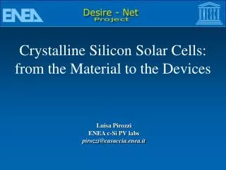
Crystalline Silicon Solar Cells: from the Material to the Devices Luisa Pirozzi ENEA c-Si PV labs pirozzi@casaccia.enea.it
ENEA Crystalline Si PV laboratory – Rome http://wwwcas.casaccia.enea.it/sicri/ - -
I • -Introduction • Cell Design • -Silicon technology • II • -Cell fabrication processes • Crystalline Silicon Solar Cells
1839 (Becquerel): light-dependent voltage between electrodes immersed in an electrolyte 1941: first Silicon solar cell (announced in 1954) 1958: first space applications
SUNLIGHT FRONT CONTACT (GRID) ANTIREFLECTIVE COATING N - REGION + DEPLETION LAYER LOAD _ + _ + _ P - REGION BACK CONTACT • PV cell structure: • p-n junction with upper electrode shaped as a grid to allow light (photons) transmission • incident photons having energy higher than the band gap of the semiconductor are absorbed in the material generating electron and hole pairs • carriers created at distance less than the diffusion lenght from the depletion layer are separated by the electric field there existing and a potential difference arises across the junction • if the device is connected to a load the photoinduced voltage allows a current flow in the load
Energy distribution (W/m2 / mm) 2000 1000 2.5 1.1 wavelengthl (mm) 0.3 nh - Eg nh < Eg net energy Spectral distribution of sunlight
As for IC, Silicon is not the best material for solar cells: band-gap too narrow and low absorption coefficient (indirect gap) 35 30 GaAs Single crystalline Si 24,7% 25 20 Eff (%) Multicrystalline-Si 19,8% 15 10 5 0 0 0,5 1 1,5 2 2,5 3 3,5 4 Eg (eV)
ARC GRID REGION N REGION P
I Isc Im Pm = Vm Im V Vm Voc PV CELL PARAMETERS IL=photogenerated current I0=diode saturation current q=electron charge Rs=series resistance n=diode ideality factor (1 - 2) k=Boltzmann’s constant Isc =short circuit current Voc=open circuit voltage Pm=maximum power output= Vm Im FF=Fill Factor=Pm / Isc * Voc h =efficiency =Pm / Pin= Voc IscFF/ Pin Pin=total power of incident light
Amp. Amp. I1 = 1 kW/m2 T1 = 20°C I2 = 0,5 kW/m2 T2 = 60°C Volt Volt I-V curves at different light Intensities I-V curves at different Temperatures 4 4 3 3 2 2 1 1 0 0 0,0 0,2 0,4 0,6 0,8 0,0 0,2 0,4 0,6 0,8
- the cell design must take into account its application: Production-terrestrial, space, concentration,architecture, etc Lab- high efficiency, theoretical limit -process lay-out: from three to more than 20 steps production line –clean room • -Si cells theoretical efficiency limit: 27% • Record efficiency: 24.7% • Average efficiency (production): 14.5%
Cell Parameters • Jsc- short circuit current • optical absorption • base recombination (red light) • emitter recombination (blue light) • Voc- open circuit voltage • bulk recombination (Job) • emitter recombination (Joe) • Space charge region (Jor) • Fill Factor • Ideality factor (n) • Series resistance (Rs) • Shunt resistance (Rsh)
To optimise cell efficiency: • Increase carriers generation • Increase carriers collection Losses: recombination, resistive Resistive: Bulk Emitter Back Contact grid Shunt Recombination: Joe: Front surface Emitter Jr: space charge region Job: Base Back
Crystalline Silicon over 90% of world-wide solar cell production (1400 MW in 2005) Second most abundant element Only semiconductor employed in microelectronic industry Large-scale production/Technology coming from microelectronics
Silicon is the second most abundant element, but about half of the cell cost is due to the substrate. • Silicon production steps: • From sand to metallurgical-grade Silicon (MG-Si) • MG-Si to semiconductor-grade Silicon (SeG-Si) • Crystal growth
Solar grade silicon “sand” coke HCl UMG-Si SiHCl3 poly Siemens Process Fluid bed Reactor Arc Furnace Ingots for electronics Scraps Low quality 60 $/kg 15 - 30$/kg 1-2 $/kg Single crystal Multi crystal Silicon
Metallurgical-grade Silicon (MG-Si) • Due to the relative impurity of sand, quartzite – 99% SiO2- is the starting material. • Silicon is produced in an Arc Furnace, at T about 1900°C, reducing SiO2 by Carbon ( coke, coal and wood chips): • SiO2 + 2C Si + 2 CO • Liquid silicon is poured into shallow troughs. • MG-Si 98% pure (major impurities Fe and Al). • Cost 1-2$/Kg
Semiconductor grade Si (SeG-Si) • For use in electronics, impurities must be almost completely removed • MG-Si purification (Siemens process) • MG-Si is converted to a volatile compound • Si + 3HCl = SiHCl3 + H2 • Trichlorosilane is produced by multiple fractional distillation • SeG-Si is obtained reducing Trichlorosilane by H2: • SiHCl3 + H2 = Si + 3HCl • Result: polysilicon
Crystal Growth • Silicon for electronic industry must be not only impurity-free, but also a single crystal, defect-free. • Poly-Si is molten and grown into single-crystal ingots: • Czochralsky (CZ) • Floating Zone (FZ)
Czochralsky (CZ) method • SeG polycrystalline Si is molten in a crucible, at T=1410 °C • A crystal seed is dipped into the molten Si and pulled slowly out of the melt in the vertical direction while rotating: • crystallization at solid/liquid interface • SeG- Si residual impurities are confined in liquid phase • dopants (B, P) can be added to the melt • Ld=200 mm t=15 msec
Floating Zone (FZ) Method • A zone of molten Si is slowly passed along the length of a poly-Si ingot. • Material melts at one boudary and recrystallizes at the other. • High purity regrown Si crystal:no crucible, liquid region prevents impurity from entering the growing crystal • Ld>500 mm t>100 msec
Microelectronics 1 Si wafer for >106 chips • Photovoltaic 1 Si wafer for 1,5Wp ; 1,5KWh/year • PV application requirements much less severe than in electronics: • -impurity levels • -carriers transport properties • Silicon especially developed for PV: • Multi-crystalline Si Ribbon Solar grade Si
Multi-crystalline Si • -Crystalline grains random oriented. • -Grain boundaries: recombination centers - shunt paths for current. • -Columnar structures and large grains (some mm): comparable to single-crystal • Ld>150 mm t>10 msec • Production less expensive • 55% Si cells production on mc-Si (record EFF: 19,8%)
Multi-crystalline Silicon Casting -starting material: scraps of ingots for microelectronics, molten in a quartz crucible. - DS method: Solidification starts from the bottom: columnar ingot growth. Ld 200 mm t >10 msec
Ribbon • Almost half of the material is lost during wafering. • Silicon is grown in ribbons (250-300 mm) • EFG method (Edge-defined-Film-fed-Growth): • Molten Silicon moves up the interior of a grafite die by capillarity.
hN at/cm3 Solar grade Silicon • -some metallic impurities can be present in concentrations>1015/cm3 (100 times > SeG-Si) • Preparation of Silane (SiH4) from metallurgical grade Si • -Deposition of Si from SiH4
Emitter formation Ohmic Contacts AntiReflection treatments
ARC GRID REGION N REGION P Emitter • photogeneration in blue region of spectrum • collection of photogenerated carriers • shallow, lightly doped, passivated (low recombination) • Contribution to Series Resistance: • deep, heavily doped • Compromise: junction profile
n/p Junction -thermal diffusion of dopant atoms into the silicon (p doped during growth)
Doped Oxide, spin-on, screen printing, thin films Solid Diffusion source: laser Liquid Open tube Gaseous Phosphorous thermal Diffusion in Silicon -Phosphorus: most used Fick laws: I) J= -D grad C II) C/ t = D 2C/ x2 J = flux C = concentration
Exhaust Quartz tube POCl325 ºC Silicon Wafers Quartz Thermostat Mass flowmeters N2p O2 Reactive Gas Carrier Gas Carrier Gas N2 • “open tube” diffusion: • Predeposition on wafer surface • Drive-in: P atoms diffusion • T: 800-1000 °C; N2 and O2
Source: POCl3 2POCl3 + 3/2O2 P2 O5+3 Cl2 Si + O2 SiO2 5Si + 2P2 O5 5SiO2 +4P SiO2:better control of diffusion process
Concentration profile: • C(x,t)=Cs erfc(x/2Dt) • D= D0 exp (-E/KT) P diffusion coefficient in Si (10-14 cm2/seca 980 ºC) • Temperature, time duration and dopant source determine: • -P surface concentration,Cs • -xj=junction depth • -resistance and t of diffused region • when Cs > P solubility limit (1021 at/cm3 a1000ºC) • dead layer: high defect density region , low t
Laser Assisted Doping laser beam creates dopant atoms (PCl3 pyrolysis or solid source) and simultaneously induces melting of silicon: dopant liquid phase diffusion. Localized process, low thermal budget Fast diffusion kinetics
TEM picture of laser doped silicon after re-crystallization Dopant concentration profile
Surface Passivation • Surface: critical discontinuity in the crystal structure • High density of allowed states within the forbidden gap • Silicon: surface-state density reduced growing passivating oxide • -interface between oxide and Si moves towards bulk • Thermal Oxidation: open tube, in O2 at T 800-1000 °C • low T alternative: SiN layer
Ohmic Contacts • Front contact must minimize series resistance losses, providing at the same time the maximum light amount to reach the cell surface. • A good back contact allows to increase Jsc and Voc (confinement techniques). • -Good ohmic contact metal/silicon • Low metal resistivity
Ohmic Contacts • Front Grid: • Busbar are directly connected to the external load • -Fingers collect current to delivery to a busbar. Rs=Rbase+Remitter+Rgrid
Contact technologies - photolitography vacuum evaporation -screen printing - electrochemical growth
metal Silicon Metal/Si contact -Schottky barrier High contact resistance -ohmic contact is obtained by reducing barrier width: tunneling - high P concentration at Si surface can reduce barrier width: Highly doped emitters Alloying Annealing at T 450-800 °C
Photolitography • - photosensitive polymer is deposited on wafer surface • Regions to metallize are exposed through a mask to UV light • - Vacuum evaporation • Front:Ti (400 A) adherence to Si • Pd (200 A) barrier layer • Ag 1-5 mm good conductivity • Back: Al 1mm • -Lift-off: photoresist removed in acetone • -Annealing: 400- 600 °C N2 or forming gas • ohmic contact • Resolution: few microns • Shadowing < 4%
Screen printing • -contact grid is obtained by depositing on wafer surface, through metal screens, inks or conductive pastes • -inks contain metal grains (Ag, Al), glasses, organic binders and solvent • Firing: • In a belt furnace, the glass melting temperature (about 800°C) is reached for few minutes • Contact to Si: alloy metal/Si (Al)through glass matrix (Ag) • Resolution: 80-100 micron • Shadowing:10%
Selective Emitter • Heavy doped emitter : • low response in blue region -“dead layer”, photogenerated carriers have low probability to be collected- • Selective emitter: • regions under contacts are heavy doped, to reduce Rc • Exposed region is low doped to increase collection in blue spectral portion • - double diffusion, laser doping
(a) (b) Si Seff Sb Si Sf p+ Al/Si-liquid Al-layer p e- p T=25C T 577C (d) (c) n+ Bulk BSF p-Si p-Si p+-Si EF p+-Si Al/Si-liquid Al/Si-layer T 577C cooling T 577C cooling Emitter Wb WBSF Back Surface Field
AntiReflection treatments • Silicon reflects 35% of incident light, and up to 54% at short l (high refractive index n) • Techniques to reduce losses: • -Deposition of one or more layers of thin oxides • - Surface Texturization
Thin AR layers • losses due to reflection can be drastically reduced