Download

1 / 24
240 likes | 351 Views
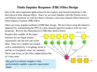
Learn about the theory behind Infinite Impulse Response (IIR) filters, including their properties, coefficient calculation, structure selection, and implementation in Matlab, C, and linear assembly.

E N D
Chapter 15 Infinite Impulse Response (IIR) Filters
Learning Objectives • Introduction to the theory behind IIR filters: • Properties. • Coefficient calculation. • Structure selection. • Implementation in Matlab, C and linear assembly.
Introduction • Infinite Impulse Response (IIR) filters are the first choice when: • Speed is paramount. • Phase non-linearity is acceptable. • IIR filters are computationally more efficient than FIR filters as they require fewer coefficients due to the fact that they use feedback or poles. • However feedback can result in the filter becoming unstable if the coefficients deviate from their true values.
Properties of an IIR Filter • The general equation of an IIR filter can be expressed as follows: • ak and bk are the filter coefficients.
Properties of an IIR Filter • The transfer function can be factorised to give: • Where: z1, z2, …, zN are the zeros, p1, p2, …, pN are the poles.
Properties of an IIR Filter • The transfer function can be factorised to give: • For the implementation of the above equation we need the difference equation:
Properties of an IIR Filter IIR Equation IIR structure for N = M = 2
Design Procedure • To fully design and implement a filter five steps are required: (1) Filter specification. (2) Coefficient calculation. (3) Structure selection. (4) Simulation (optional). (5) Implementation.
Coefficient Calculation - Step 2 • There are two different methods available for calculating the coefficients: • Direct placement of poles and zeros. • Using analogue filter design. • Both of these methods are described.
Placement Method • All that is required for this method is the knowledge that: • Placing a zero near or on the unit circle in the z-plane will minimise the transfer function at this point. • Placing a pole near or on the unit circle in the z-plane will maximise the transfer function at this point. • To obtain real coefficients the poles and zeros must either be real or occur in complex conjugate pairs.
Placement Method • Example - Placement method: • Link: \Links\zeropole.exe
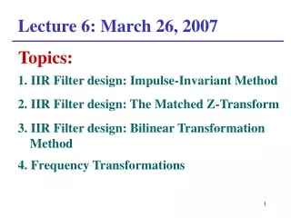
Analogue to Digital Filter Conversion • This is one of the simplest method. • There is a rich collection of prototype analogue filters with well-established analysis methods. • The method involves designing an analogue filter and then transforming it to a digital filter. • The two principle methods are: • Bilinear transform method (\Links\Bilinear Theory.pdf). • Impulse invariant method.
Bilinear Transform Method • Practical example of the bilinear transform method: • The design of a digital filter to approximate a second order low-pass analogue filter is required. • The transfer function that describes the analogue filter is: • The digital filter is required to have: • Cut-off frequency of 6kHz. • Sampling frequency of 20kHz.
Bilinear Transform Method • Matlab code for calculating coefficients: a = tan(pi*2/8) % cut-off 2kHz, fsample 8 kHz, input < 580 mVpp b = (1 + 2^0.5 + (a*a)) b00 = (a*a)/b b01 = 2*b00 b02 = b00 a01 = 2*(a^2 -1)/b a02 = (1 + a^2 - (2^0.5)*a)/b bb = [b00 b01 b02]; aa = [1 a01 a02]; figure(1) freqz(bb,aa,512,8000) fid = fopen('IIR_coef_float.txt', 'w'); fprintf(fid,'%0.4f,%0.4f,%0.4f\n',bb); fprintf(fid,'%0.4f,%0.4f\n',aa); fclose(fid);
Bilinear Transform Method • Output from Matlab code: • bb = [0.2929, 0.5858, 0.2929] • aa = [1, --1.3007e-016, 0.1716] • Converting these to Q15 format we get: • b = (bb * 215)HEX = [0x257D, 0x4AFB, 0x257D] • a = (bb * 215)HEX = [0x7FFF, 0x0, 0x15F6] • Note that 1 ~ (0x7FFF)DEC
Realisation Structures - Step 3 • Direct Form I: • Difference equation: • This leads to the following structure…
Realisation Structures - Step 3 • Direct Form I:
Realisation Structures - Step 3 • Direct Form II canonic realisation: • Where: • Taking the inverse of the z-transform of P(z) and Y(z) leads to:
Realisation Structures - Step 3 • Direct Form II canonic realisation:
Implementation - Step 5 void IIR_Isr (void) { short a1 = 0x0; short a2 = 0x15f6; short b0 = 0x257d; short b1 = 0x4afd; short b2 = 0x257d; static short d01=0, d02=0, d00; short xn, y0; int prod1, prod2, prod3, prod4, prod5, input, output; input = mcbsp0_read(); // Read the input sample from the serial port y0 = 0; input &= 0xffff; xn = (short) (input & 0x000ffff); prod1 = _mpy(d02,a2)>>15; prod2 = _mpy(d01,a1)>>15; d00 = xn + (short)(prod1 + prod2); prod3 = _mpy(d01,b1); prod4 = _mpy(d02,b2); prod5 = _mpy(d00,b0); y0 = (short)((prod3+prod4+prod5)>>15); d02 = d01; d01 = d00; output = y0; mcbsp0_write(output& 0xfffffffe); // Write the signal to the serial port return; } ‘C’ code
Implementation - Step 5 .def _iir_sa .sect "mycode" _iir_sa .cproc an1, an2, bn0, bn1, bn2, delays, x_ptr, y_ptr,mask, mask2 .reg p0, p1, p2 .reg prod1, prod2, prod3, prod4, prod5 .reg sum1, sum2, sum3 .reg x, ref, y0,y1 LDW *x_ptr, x AND x,mask,x LDH *+delays[0], p1 LDH *+delays[1], p2 MPY an1, p1, prod1 MPY an2, p2, prod2 ADD prod1, prod2, sum1 SHR sum1, 15, sum1 ADD x, sum1, p0 MPY bn0, p0, prod3 MPY bn1, p1, prod4 MPY bn2, p2, prod5 ADD prod4, prod5, sum2 ADD prod3, sum2, sum3 SHRU sum3, 15, y0 STH p1, *+delays[1] STH p0, *+delays[0] AND y0, mask2, y0 STW y0, *y_ptr .return y0 .endproc Linear assembly code
IIR Code • Code location: • Code\Chapter 15 - Infinite Impulse Response Filters • Projects: • Fixed Point in C: \IIR_C_Fixed\ • Fixed Point in Linear Asm: \IIR_Sa_Fixed\
Chapter 15 Infinite Impulse Response (IIR) Filters - End -