
Methodology
E N D
Presentation Transcript
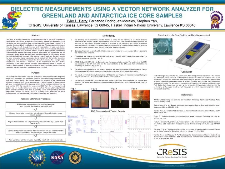
DIELECTRIC MEASUREMENTS USING A VECTOR NETWORK ANALYZER FOR GREENLAND AND ANTARCTICA ICE CORE SAMPLESTyler L. Berry, Fernando Rodriguez-Morales, Stephen Yan, CReSIS, University of Kansas, Lawrence KS 66045, Haskell Indian Nations University, Lawrence KS 66046 Build a planar transmission on the surface of a sample (e.g., microstrip line, co-planar waveguide, etc) Construction of a Test Bed for Ice Core Measurement • Methodology • The first step was to determine a suitable material to create the test stand out of and for its dielectric properties to not interfere with the measurements of the ice cores. The dielectric constant needed to be less than 3.0 but it would be more beneficial to be closer to 2.0. We could get a rough estimate of materials dielectric constants from tables researched on the internet. The results had tolerances on some materials too wide to make a good estimate on whether they were suitable. • Samples of materials were ordered that had a price range suitable for our purposes and then prepared to test their dielectric constants. • Copper tape was covered on one side of the material and a 3/8 inch strip of copper tape placed down the center on the reverse side (Fig. 1 and 2). • A PCB Endlaunch SMA .042 inch Connector was then soldered to the sample. The center pin of the SMA was soldered to the 3/8 inch strip and the outer conductor of the SMA was then soldered to the completely covered side (Fig. 3 and 4). • The information gathered from the Network Analyzer was transferred to the Agilent Advanced Design System program (ADS) on a computer and the dielectric constant of the material was derived. • The results of the High Density Polyethylene (HDPE) (2.16) and the price of materials were satisfactory to our purpose and it was decided to use this material for our platform. • The design in SolidWorks “Computer Animated Design (CAD)” was determined after the material was selected. The design was determined based on material characteristics and material size that could be purchased. Measure the complex transmission and reflections (S21 and S11) with a vector network analyzer • Abstract • Sea level is strongly linked to the growth and shrinkage of the large ice sheets in Greenland and Antarctica. There is an urgent need to improve both knowledge of ice dynamics and accuracy of ice-sheet models to predict the ice-sheets’ response to a warming climate and their contribution to sea level rise. A key component to improve the ice sheet models through the use and interpretation of radar data is the knowledge of the dielectric properties of the ice. Most of the measured data on the dielectric properties of ice available today is based on measurements performed at low frequencies with the technology available in the 1960s and again in the 80s. In this project we will design and fabricate a set of test fixtures to characterize relative permittivity of dielectric materials using a vector network analyzer. One technique to be used relies on a planar transmission line in contact with the sample, where the sample acts as a dielectric loading to the line. By measuring the change in the transmission and reflection coefficients of the transmission line, the relative permittivity of the sample can be retrieved. The method will serve as a basis for dielectric measurements on dielectric materials in the 10-1000 MHz range and will be used as a test bench for future measurements on ice cores. Plug the measured data into a high-frequency circuit simulator (e.g., Agilent ADS, Ansys HFSS) Develop an equivalent circuit model of the transmission line and parameterize the dielectric constant (r) and loss tangent (tan) in the model Conclusion Further testing is required after the construction of the test platform to determine if the material and dimensions will be sufficient. Test samples will be used in substitution of the ice cores to see how it well it employs the return data. After final testing we will use the measured dielectric data of the ice cores to simulate radar returns at existing core sites and compare these returns with experimental results. We will perform measurements of existing ice cores in collaboration with Prof. Dorthe Dahl-Jensen and her team at the University of Copenhagen. After verifying the performance of the probe, we will convert the system to perform measurements in the field on new cores to be drilled. Purpose To develop and demonstrate a system for dielectric measurements in the frequency range of 10-1000 MHz. This system will consist of a coplanar waveguide test platform (See Test Platform Model). An ice core sample can be place on the platform and impedance measurements can be performed with a vector analyzer. The test platform will allow characterization of the samples without further cutting or slicing of the ice core sample. With the accurate ice core-derived DEP from the new measurement system, we can invert existing radar data as well as the new ultrawideband radar depth sounder (150-600 MHz) that is currently under development by CReSIS (deployment planned for winter 2013) to unambiguously determine the basal conditions over many areas of the Ice Sheets in Greenland and Antarctica. Fig. 4 Fig. 3 Tune r and tan until the simulated S21 and S11 match with the measured data References WCRP, “Understanding sea-level rise and variability”, Workshop Report. IOC/UNESCO, Paris, France, June 6-9, 2006. Dahl-Jensen, D. et al., “Eemain interglacial reconstructed from a Greenland folded ice core,” Nature, vol. 493, pp. 489-494, 2013. Van der Veen, C.J. and ISMASS Members, “A Need for More Realistic Ice-Sheet Models,” SCAR Report No.30, 2007. Evans, S., “Dielectric properties of ice and snow – a review,” Journal of Glaciology, vol. 5, no. 42, pp. 773-792, 1965. Fujita, S., Shiraishi, M., and Mae, S., “Measurement on the dielectric properties of acid-doped ice at 9.7 GHz,” IEEE Transactions on Geoscience andRemote Sensing, vol. 30, no. 4,pp. 799-803, 1992. Wilhelms, F., et al., “Precise dielectric profiling of ice cores: a new device with improved guarding and its theory,” Journal of Glaciology, vol. 44, no. 146, pp. 171-174, 1998. Havrilla, M. J., and Nyquist, D. P., “Electromagnetic characterization of layered materials via direct and de-embed methods,” IEEE Transactions on Instrumentation and Measurement, vol. 55, no. 1, pp. 158-163, 2006. General Estimation Procedure ADS Simulated and Tested Results Fig. 2 Fig. 1