Download
1 / 39
390 likes | 533 Views
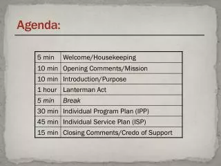
Agenda – Day 1. 8:00 am – 8:15 am Introductions and House Keeping 8:15 am – 8:45 am Session 1: Load Rating Basics 8:45 am – 9:30 am Session 2: Basic Load Rating Calculations 9:30 am – 9:45 am Break 9:45 am – 11:45 am Session 3: Example – Load Rating Concrete Slab Bridge

E N D
Agenda – Day 1 8:00 am – 8:15 am Introductions and House Keeping 8:15 am – 8:45 am Session 1: Load Rating Basics 8:45 am – 9:30 am Session 2: Basic Load Rating Calculations 9:30 am – 9:45 am Break 9:45 am – 11:45 am Session 3: Example – Load Rating Concrete Slab Bridge 11:45 am – 12:00 pm Questions 12:00 pm – 1:00 pm Lunch 1:00 pm – 2:30 pm Session 4: Example – Load Rating Steel Beam Bridges 2:30 pm – 2:45 pm Break 2:45 pm – 3:45 pm Session 4: Example – Load Rating Steel Beam Bridges (Con’t) 3:45 pm – 4:00 pm Questions Load Rating Seminar
Section Loss on Steel Beams • Field measure section loss on steel beams. • Section loss reduces the capacity of steel beams. • The location of section loss on the beam is important • Location on the beam (web & flanges) • Location along the length of the beam • Capacity and Loads (DL & LL) must be calculated at the same location
Example calculation with Section Loss Exterior beam example calculation Single –span W33x130 Built in 1968 Fy = 33,000 psi Original Section per AISC Manual
Estimated Section Loss Located: 20 ft. from Centerline Bearing Step 1: Calculate Capacity of Beam with section loss.
Establish Approximate Section Dimensions for Load Rating Calculations: Use Section Loss Estimates and Field Measurements
Find distance from bottom of section to the Plastic Axis: Recall that the plastic axis divides the top and bottom half areas of the section.
What if the section does not qualify as compact? Use the Elastic Section Modulus (S) instead of the Plastic Section Modulus (Z).
Find the Neutral Axis, Moment of Inertia (I), and Section Modulus (S):
Timber Decks on Steel Beams • Timber deck does not supply continuous support to the compression flange of the steel beam • Compression flange of the steel beams is braced only at the diaphragms/crossframes.
Capacity of Beam w/ Timber Deck • Beams will be one of the following: • Compact • Braced Noncompact • Partially Braced Noncompact • Follow flowchart to determine beam capacity
Flowchart to Determine Capacity of Steel Beams on Timber Deck • Check for Compactness – check 3 equations • Equation 10-93 • ≤ • Equation 10-94 • ≤ • Equation 10-96 • ≤
Flowchart to Determine Capacity of Steel Beams on Timber Deck • If all three equations are satisfied then beam is compact and: Mu = Fy Z • If all three equations are Not satisfied then check for braced Noncompact.
Flowchart to Determine Capacity of Steel Beams on Timber Deck • Check three equations for Braced Noncompact: • Equation 10-100: • ≤ 24 • 2 Web thickness not less than D/150 • tw > D/150 • Equation 10-101: • Lb ≤
Flowchart to Determine Capacity of Steel Beams on Timber Deck • If all three equations are satisfied then beam is braced noncompact and Mu equals the lesser of: • 1. Mu = FySxt • 2. Mu = FcrSxcRb • SxtFcrSxc & Rb are defined in AASHTO Section 10.48.2
Flowchart to Determine Capacity of Steel Beams on Timber Deck If all three equations are not satisfied then beam is partially braced noncompact and Mu equals: Mu = MrRb Rb is calculated using equation 10-103b Mr is calculated using one of the following equations based on the unsupported length: Equations: 10-103c, 10-103d, 10-103e, 10-103g
Example Data • Beam spacing = 3.0 ft. • Diaphragm spacing = 5.0 ft. • Timber Deck = 3” x 6” planks • Beam size = W21 x 62 • Fy = 50,000 psi • Span length = 50.0 ft.