Download
1 / 9
100 likes | 214 Views
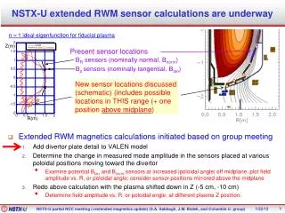
EMMA resistive wall monitor (RWM). Jim Crisp October 2007. Uses. bunch amplitude bunch phase or timing map synchrotron oscillations through 15 turns bunch shape. RWM ceramic details. Microwave cutoff in beam tube defines upper frequency limit 3.7GHz for 48mm ID round pipe

E N D
EMMA resistive wall monitor(RWM) Jim Crisp October 2007
Uses • bunch amplitude • bunch phase or timing • map synchrotron oscillations through 15 turns • bunch shape
RWM ceramic details • Microwave cutoff in beam tube defines upper frequency limit • 3.7GHz for 48mm ID round pipe • difficult/impossible to separate signals propagating along beam pipe • 4 equally spaced pickoff points provide a measurement reasonably independent of beam position and rejects non TEM modes • Use resistive combiners on flexible circuit board • radial mode in ceramic • εr=8.9 for 94% Alumina • 377/sr(8.9) = 126.4ohms/square • For 48mm ID pipe estimate ceramic to be 70mm OD 60mm ID • 5mm wall is ¼ wavelength at 5.0GHz • ideal impedance for 3mm long ceramic gap • 2.0ohms = 126.4*3mm/(65mm) • rwm • microwave chip resistors and flexible circuit board used to form resistive combiner are good for ~10GHz • Tested with 50ohm structure that has higher cutoff frequency
RWM ferrite details • peak current 130mAmps • 20pC in 60pSec bunch • 2ohm gap would provide reasonable signal (260mVp) • desire time constant much longer than 830nsec • (15 turns at 55.3nsec/turn) • Ceramic Magnetics MN100 ferrite core • u=10000 • 130mm OD, 80mm ID, 25mm Ht • L=N^2 uA/L = 24uH (N=1) • 2ohm 24uH = 12uSec (13.4KHz)
something like this • Outer ceramic rings • Required for manufacture • Metalized to provide electrical contact • Used to mount flexible circuit board • Need additional room for • Vacuum flanges • and bolts • Electrical shield • Signal connections
Cable Dispersion • Recommend 7/8” Heliax (Andrew LDF5-50A) • higher order modes above 5GHz • 1.254db/100ft @ 1GHz • v/c = 0.89 • (dispersion is less for larger cable but higher order modes become a problem) • red trace on left estimates cable dispersion for 60ps bunch • red trace on right estimates 4GHz LPF for 60ps bunch
correcting errors • To some extent… repeatable errors such as cable dispersion and limited bandwidth can be corrected in software. • This can be done in the frequency domain or with an FIR filter in the time domain
Tektronix ‘DPO71254’ Windows based operating system 4 channels 50Gs/s 10Meg 200usec of memory 12.5GHz bandwidth 23psec risetime 10mV to 1V/div 10ps to 1000s/div $88500 4 week lead time Agilent ‘DSO81204’ Windows based operating system 4 channels 40Gs/s 4Meg (opt 001) 100usec of memory 12.0GHz bandwidth 26psec risetime 1mV to 1V/div 10ps to 1000s/div $92538 (+$5184 opt 001) 5 week lead time possible oscilloscopes
RWM summary • Expect 3 to 4 GHz bandwidth limited by the size of the beam pipe • Can the pipe be less than 48mm? • 13KHz (12usec) on the low end • parts for RWM are roughly $5k • consider purchasing a second scope for a spare and to allow software development. • 2 X $100k