Download

1 / 49
490 likes | 680 Views
P09141 Satellite Thermal Heater Controller. Anthony Berwin Mechanical Engineer Scott Rioux Industrial Engineer Greg Pawlowski Electrical Engineer Sarmad Abedin Electrical Engineer John Scipione Electrical Engineer Sponsors: ITT Corporation & D3 Engineering.

E N D
P09141Satellite Thermal Heater Controller Anthony Berwin Mechanical Engineer Scott Rioux Industrial Engineer Greg Pawlowski Electrical Engineer Sarmad Abedin Electrical Engineer John Scipione Electrical Engineer Sponsors: ITT Corporation & D3 Engineering KGCOE Multidisciplinary Senior Design
Project Overview • Description: Thermal Controller for Satellite Operations • Market: Space Systems Division of ITT • Key Deliverables: • Power Efficiency • Mass • Performance • Communications • Cost KGCOE Multidisciplinary Senior Design
Project Concept • Enclosure • Interface Board • Communications • Programming • Protocol • GUI KGCOE Multidisciplinary Senior Design
Project Architecture KGCOE Multidisciplinary Senior Design
Milestones • MSD 1 • January 16, 2009 – System Level Design Review • February 13, 2009 – Detailed Design Review • February 20, 2009 – Project Presentation • MSD II • March 9, 2009 – Begin Programming DSP & GUI • March 13, 2009 – Materials Ordered • April 3, 2009 – Testable Prototype • May 1, 2009 – Testing & Debugging Completed • May 20, 2009 – Final Review KGCOE Multidisciplinary Senior Design
Budget/BOM • Original Budget: $1740 – $2070 • Current Estimated Budget: $1703.44 • All components available • Shipping time 1-2 weeks • Waiting on DSP’s • Machine time for Enclosure 2 weeks, could outsource for faster turn around time KGCOE Multidisciplinary Senior Design
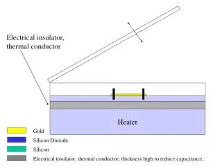
EnclosureNeeds & Specifications • Size (Minimize) • Mass (<0.3 lb) • Mounting (Enclosure, PCB, Connectors*) • Vibrations (23.1 G’s Random Vibration) • Thermal (-40°C to +55°C) • Vacuum Environment • Ventilation* (<1 psi/s) • Outgassing • Torque on Screws* • EMI Leakage* (<100 kHz) KGCOE Multidisciplinary Senior Design
EnclosureAssembly Model KGCOE Multidisciplinary Senior Design
EnclosureAssembly Model: Exploded View Top PCB Side A Side B Base KGCOE Multidisciplinary Senior Design
EnclosureSpecifications Met • Total Size: 2.875” x 2.875” x 1.0625” • Size of the PCB with the Connectors: 2.61” x 2.25” x 0.5625” • Total Mass: 0.244 lb • 18% below the 0.3 lb limit • Enclosure Mounting: • Flat Plate & Cylinder (R>18”) • PCB Mounting: • Four (4) Screws & Aluminum Heat Sink Contacts KGCOE Multidisciplinary Senior Design
EnclosureSpecifications Not Met • Partially Met • Connector Mounting • Vacuum Environment • Ventilation • Outgassing • Not Met • Torque on Screws • EMI Leakage KGCOE Multidisciplinary Senior Design
EnclosureRisk Assessment: Risks • Acquiring PCB Specifications • Acquiring Connector Specifications • Acquiring Equipment (PCB & Connectors) • Stress on the Screws • Enclosure Strength KGCOE Multidisciplinary Senior Design
EnclosureRisk Assessment: Actions • Acquiring PCB Specifications • Delay in the redesign of the enclosure or causing a redesign much later in MSD II • Acquiring Connector Specifications • Delay in the redesign of the enclosure or causing a redesign much later in MSD II • Acquiring Equipment (PCB & Connectors) • Delay in the assembly of the enclosure • Stress on the Screws • Failure during vibrations testing • Enclosure Strength • Failure during vibrations testing KGCOE Multidisciplinary Senior Design
EnclosureRisk Assessment: Mitigation • Acquiring PCB Specifications • Work with the customer to clarify specifications • Acquiring Connector Specifications • Work with the customer to clarify specifications • Acquiring Equipment (PCB & Connectors) • Work with the customer to receive the equipment • Stress on the Screws • Increase screw size • Use temporary thread-locking adhesive • Enclosure Strength • Change material to aircraft aluminum KGCOE Multidisciplinary Senior Design
EnclosureAction Items • Redesign of the enclosure • Increase screw size • Change material to aircraft aluminum • Final PCB Specifications • Complete • Part Models • Assembly Model • Part Drawings • Parts List • BOM • Enclosure Specifications • Thermal and Vibrations Simulations KGCOE Multidisciplinary Senior Design
Interface BoardOverview • Purpose • Master and slave communications over a power bus • Isolation from 28VDC Power Bus • Transmit/Receive Switching • Transmit/Receive Signal Conditioning • Voltage conversion KGCOE Multidisciplinary Senior Design
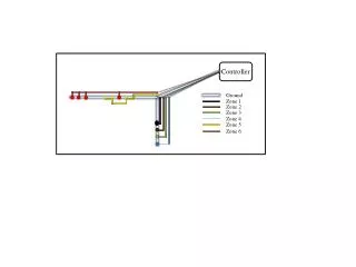
Interface Board Block Diagram KGCOE Multidisciplinary Senior Design
Interface Board DC Isolation • Need • There are no dedicated communication lines • RF signals will interfere with other satellite operations • Power bus already available • Isolation of communications signal from DC power bus to protect electronics KGCOE Multidisciplinary Senior Design
Interface Board Switching • Need • Transmitting the communications signal • Receiving the communications signal • It is necessary to switch between the two modes of operation KGCOE Multidisciplinary Senior Design
Interface Board Voltage Converter • Need • Negative supply voltage to operate electronics on interface board • Will take a input voltage and output the same negative voltage KGCOE Multidisciplinary Senior Design
Interface Board Receive Signal Conditioning • Need • Filter out noise from communications signal • Amplify communications signal for ADC • Offset communications signal to positive voltage for ADC KGCOE Multidisciplinary Senior Design
Interface Board Transmit Signal Conditioning • Need • Filter out high frequency harmonics from communications signal • Generate the communications signal from pulse width modulator KGCOE Multidisciplinary Senior Design
Interface Board Risk Assessment: Risks • Low frequency noise not filtered out • Transient noise not accounted for • Power consumption of IC’s • Design of filters KGCOE Multidisciplinary Senior Design
Interface Board Risk Assessment: Actions • Low frequency noise not filtered out • Communication errors, or signal not received • Transient noise not accounted for • Communication errors, or signal not received • Power consumption of IC’s • Use to much power, other systems will not work • Design of filters • Filters do not function properly KGCOE Multidisciplinary Senior Design
Interface Board Risk Assessment: Mitigation • Low frequency noise not filtered out • Transient noise not accounted for • Write better demodulation algorithm, use more hardware demodulation techniques • Power consumption of IC’s • Switch to low power modes when not in use • Design of filters • Do more research on filter design, or seek help in filter design from experienced engineers KGCOE Multidisciplinary Senior Design
Interface Board Action Items • Finalize parts for interface board • Build prototype and test KGCOE Multidisciplinary Senior Design
ProgrammingArchitecture KGCOE Multidisciplinary Senior Design
ProgrammingNeeds • PC communicate with Master DSP over serial line. • Master DSP communicate with each slave over 28V heater power bus. No dedicated lines are available. • Modulation and demodulation is needed. KGCOE Multidisciplinary Senior Design
Programming DSP • The bits of the protocol must be generated, stored, and interpreted. • A sine wave must be generated from binary usingPWM/ DAC. • Signal demodulated back into binary usingADC. • Communication with the PC GUI over SCI. KGCOE Multidisciplinary Senior Design
ProgrammingHow are we going to do it? • Code Composer will be used to Program the DSP in the C programming language. • The ADC, PWM, UART, and SCI modules are all utilized. The program is stored in flash memory. The protocol bits are stored in RAM memory. KGCOE Multidisciplinary Senior Design
ProgrammingRisks • Acquiring the DSP. Programming will be difficult to begin without the DSP. • Learning the Code Composer Environment. Code Composer comes with the DSP. • Programming each of the DSP elements that need to be programmed including PWM, ADC, the protocol, serial communication. • Finding code examples. • Writing and testing the code. KGCOE Multidisciplinary Senior Design
ProtocolCommunications • SCI protocol (LabView to Master) • 3 Pins - Transmit, Receive, Ground • 4 Transmissions - 12 Bit Each • 1 Start Bit • 8 Data Bits(Slave ID, Temp. Bits, Ctrl Bits, etc) • 1 Parity Bit (Eliminates Checksum) • 2 End Bits KGCOE Multidisciplinary Senior Design
ProtocolCommunications • UART Protocol (Master to Slave) • Bi-directional, half-duplex (only slave or master can talk at one time) • Bit by bit transmission • Different frequencies for ‘1’ and ‘0’ (in order to meet the 20 ms spec, min. freq = 5kHz; 200 us/bit) • ‘0’ frequency = 7.5 kHz • ‘1’ frequency = 17.5 kHz • No activity on line = noise only KGCOE Multidisciplinary Senior Design
ProtocolCommunications • 40 Bit Transmission • 2 Start Bits • 6 Checksum Bits • 12 Data (temp) Bits • 6 Control Bits (read/set, temp/htr state, etc.) • 5 Telemetry Pins • 8 Bits for Slave ID • 1 End Bit KGCOE Multidisciplinary Senior Design
ProtocolRisk Assessment: Risks • Transfer rate too slow • Not enough bits to account for other details • Bit/error rate too high KGCOE Multidisciplinary Senior Design
ProtocolRisk Assessment: Actions • Transfer rate too slow • Timing issues between the receiver and transmitter leading to wrong messages being transferred • Not enough bits to account for other details • Not all data will be represented and can lead to a lack of outputting required data • Bit/error rate too high • The wrong message to be transmitted and the appropriate output will not be achieved KGCOE Multidisciplinary Senior Design
ProtocolRisk Assessment: Mitigation • Transfer rate too slow • Can decrease the time it takes to send a bit • Not enough bits to account for other details • Bits will be added to protocol and the appropriate transfer rates will be calculated. • Bit/error rate too high • Reduction in signal to noise ratio must be changed or an increase in the bandwidth. KGCOE Multidisciplinary Senior Design
ProtocolAction Items • Acquiring EzDSP • Program the DSP using the FSM flowchart in order to communicate from GUI to Master and Master to Slave • Work with the interface and PWM and ADC programming to ensure proper communication KGCOE Multidisciplinary Senior Design
Graphical User InterfaceOverview • System required a simple computer interface • Needed to be able to control DSP’s and send commands • Easily readable and intuitive • Be able to control multiple parameters • Be able to communicate via Serial Port • Able to control 256 DSP’s KGCOE Multidisciplinary Senior Design
Graphical User InterfaceRisk Assessment: Risks • Time Constraints • Connectivity Problems • Testing, Replication Table • Loopback Testing • Programming Constraints • Final Implementation Requires Working DSP Programming KGCOE Multidisciplinary Senior Design
Graphical User InterfaceRisk Assessment: Actions • Time Constraints • GUI will not get completed • Connectivity Problems • Will not complete GUI to Master Link • Testing, Replication Table • Testing will be more difficult • Loopback Testing • Cannot Initiate Link over Serial • Programming Constraints • Trouble Programming in LabView • Final Implementation Requires Working DSP Programming • Final Product will not be completed in time KGCOE Multidisciplinary Senior Design
Graphical User InterfaceRisk Assessment: Mitigation • Distribution of tasks • Research and Examples • Faculty Help • Purchasing own DSP board • Discussion about final deliverables, removing requirements KGCOE Multidisciplinary Senior Design
Graphical User InterfaceConcept Selection • There were 5 candidates for GUI creation • Visual Basic • LabView • MATLAB • Java • C++ • GUI have 5 parameters in which we rated it on • Ease of Use • Safety • Programmability • Customer Preference • Familiarity • A concept selection and screening methods were both used to help determine which method would be best KGCOE Multidisciplinary Senior Design
Graphical User InterfaceConcept Selection KGCOE Multidisciplinary Senior Design
Graphical User InterfaceLabView • LabView was chosen mainly because of its ease of use, and familiarity between the team members • LabView allows us to easily create a nice GUI with multiple features • LabView is also scalable, allows us to add or change features easily without rewriting all of the programming KGCOE Multidisciplinary Senior Design
Graphical User InterfaceRequired Features • LabView needs to have visual indicators • Communicate over serial port (RS232) • Ability to see system status • Ability to set and change set points • Ability to chose between 255 slaves to upload temperature KGCOE Multidisciplinary Senior Design
Graphical User InterfaceFront Panel KGCOE Multidisciplinary Senior Design
Graphical User InterfaceCommunication • LabView will communicate with the Master via RS232 • ASCII • Four 12bit transmissions to communicate all data KGCOE Multidisciplinary Senior Design
Graphical User InterfaceAction Items • Complete Replication Table • Replication Table Parameters • Complete Communication Development from GUI to Master • Start Loop-Back Testing KGCOE Multidisciplinary Senior Design