Download
1 / 31
1.28k likes | 3.67k Views
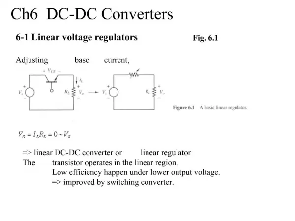
Isolated dc-dc Converters. EE514 Switched Mode Power Supplies Yrd.Doç.Dr.Mutlu Boztepe E.Ü. Elektrik-Elektronik Müh. Mart 2007. Transformer isolation. Objectives: • Isolation of input and output ground connections, to meet safety requirements

E N D
Isolated dc-dc Converters EE514Switched Mode Power Supplies Yrd.Doç.Dr.Mutlu Boztepe E.Ü. Elektrik-Elektronik Müh. Mart 2007
Transformer isolation Objectives: • Isolation of input and output ground connections, to meet safety requirements • Reduction of transformer size by incorporating high frequency isolation transformer inside converter • Minimization of current and voltage stresses when a large step-up or step-down conversion ratio is needed — use transformer turns ratio • Obtain multiple output voltages via multiple transformer secondary windings and multiple converter secondary circuits
The magnetizing inductance LM Models magnetization of transformer core material • Appears effectively in parallel with windings • If all secondary windings are disconnected, then primary winding behaves as an inductor, equal to the magnetizing inductance • At dc: magnetizing inductance tends to short-circuit. Transformers cannot pass dc voltages • Transformer saturates when magnetizing current iM is too large
Volt-second balance in LM The magnetizing inductance is a real inductor, obeying integrate: Magnetizing current is determined by integral of the applied winding voltage. The magnetizing current and the winding currents are independent quantities. Volt-second balance applies: in steady-state, iM(Ts) = iM(0), and hence
Transformer reset “Transformer reset” is the mechanism by which magnetizing inductance volt-second balance is obtained • The need to reset the transformer volt-seconds to zero by the end of each switching period adds considerable complexity to converters • To understand operation of transformer-isolated converters: • replace transformer by equivalent circuit model containing magnetizing inductance • analyze converter as usual, treating magnetizing inductance as any other inductor • apply volt-second balance to all converter inductors, including magnetizing inductance
Full-bridge and half-bridgeisolated buck converters Full-bridge isolated buck converter Sekonder 2 sargılı olarak düşünülürse , sarım oranı 1:n:n olan 3 sargılı bir transformatör gibi kabul edilebilir.
During first switching period: transistors Q1and Q4conduct for time DTs, applying voltseconds Vg DTsto primary winding • During next switching period: transistors Q2and Q3conduct for time DTs, applying voltseconds –Vg DTsto primary winding • Transformer volt-second balance is obtained over two switching periods • Effect of nonidealities?
Effect of nonidealitieson transformer volt-second balance Volt-seconds applied to primary winding during first switching period: (Vg – (Q1and Q4forward voltage drops))( Q1and Q4conduction time) Volt-seconds applied to primary winding during next switching period: – (Vg – (Q2and Q3forward voltage drops))( Q2 and Q3conduction time) These volt-seconds never add to exactly zero. Net volt-seconds are applied to primary winding Magnetizing current slowly increases in magnitude Saturation can be prevented by placing a capacitor in series with primary, or by use of current programmed mode (chapter 11)
Operation of secondary-side diodes i1(t)=0 ise; iD6 current iM << i(t) ise iD5(t)=iD6(t)=0.5i(t) • During second (D’) subinterval, both secondary-side diodes conduct • • Output filter inductor current divides approximately equally between diodes • Secondary amp-turns add to approximately zero • • Essentially no net magnetization of transformer core by secondary winding currents
Volt-second balance on output filter inductor Inductor average voltage should be zero, so; Buck converter with turns ratio
Full bridge Output voltage can be controlled by duty cycle. Duty cycle range 0<D<1 Avoid cross-conduction (Dmax is limited 0.8 in practice) Full bridge converter is typically used above 750W. Not used below, because high parts count and drive requirements Transformer primary winding is effectively utilized, but secondary is not. Diodes D1 to D4 limits transistor voltage to Vg, and provide current path for magnetizing currents, leakage currents and reactive power currents.
Half bridge isolated buck converter • Replace transistors Q3 and Q4 with large capacitors • Voltage at capacitor centerpoint is 0.5Vg • vs(t) is reduced by a factor of two • M = 0.5 nD • Transistor currents two times of full bridge.
Forward converter • Buck-derived transformer-isolated converter • • Single-transistor and two-transistor versions • • Maximum duty cycle is limited (for n1=n2 , 0<D<0.5 , will be discussed) • • Transformer is reset while transistor is off
Forward converterwith transformer equivalent circuit • Magnetizing current, in conjunction with diode D1, operates in discontinuous conduction mode (transformer reset) • • Output filter inductor, in conjunction with diode D3, may operate in either CCM or DCM
What happens when D > 0.5 magnetizing current waveforms, for n1 = n2
Maximum duty cycle vs. transistor voltage stress Maximum duty cycle limited to which can be increased by increasing the turns ratio n2 / n1. But this increases the peak transistor voltage: For n1 = n2
The two-transistor forward converter Subinterval 1 : Both transistor conduct Subinterval 2 and 3: Both transistor are off. Magnetizing current flows through D1 and D2. So, primary voltage is –Vg. Transistor blocking voltage limited to Vg Duty cycle limited to D<0.5 Typical power levels are similar to half-bridge configuration. Secondar side is identical to the single transistor version.
Push-pull isolated buck converter • Used with low-voltage input. It exhibits low primary losses, because one transistor conducts at any given instant. • • Secondary-side circuit identical to full bridge • • As in full bridge, transformer volt-second balance is obtained over two switching periods • • Effect of nonidealities on transformer volt-second balance? • • Current programmed control can be used to mitigate transformer saturation problems. Duty cycle control not recommended.
Flyback converter Isolate inductor windings: the flyback converter buck-boost converter: construct inductor winding using two parallel wires: Flyback converter having a 1:n turns ratio and positive output:
The “flyback transformer” • A two-winding inductor • Symbol is same as transformer, but function differs significantly from ideal transformer • Energy is stored in magnetizing inductance • Magnetizing inductance is relatively small • Current does not simultaneously flow in primary and secondary windings • Instantaneous winding voltages follow turns ratio • Instantaneous (and rms) winding currents do not follow turns ratio • Model as (small) magnetizing inductance in parallel with ideal transformer
CCM Flyback waveforms and solution Similar to Buck-Boost converter
Discussion: Flyback converter • Widely used in low power (50W to 100 W range) and/or high voltage applications • Low parts count • Multiple outputs are easily obtained, with minimum additional parts • Cross regulation is inferior to buck-derived isolated converters • Often operated in discontinuous conduction mode • DCM analysis: DCM buck-boost with turns ratio