IDEAL VS REAL MATERIALS
IDEAL VS REAL MATERIALS. TS << TS. engineering materials. perfect materials. • Stress-strain behavior (Room T):. Reprinted w/ permission from R.W. Hertzberg, "Deformation and Fracture Mechanics of Engineering Materials", (4th ed.) Fig. 7.4. John Wiley and Sons, Inc., 1996.

IDEAL VS REAL MATERIALS
E N D
Presentation Transcript
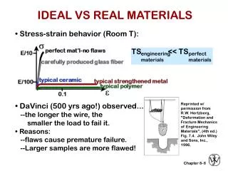
IDEAL VS REAL MATERIALS TS << TS engineering materials perfect materials • Stress-strain behavior (Room T): Reprinted w/ permission from R.W. Hertzberg, "Deformation and Fracture Mechanics of Engineering Materials", (4th ed.) Fig. 7.4. John Wiley and Sons, Inc., 1996. • DaVinci (500 yrs ago!) observed... --the longer the wire, the smaller the load to fail it. • Reasons: --flaws cause premature failure. --Larger samples are more flawed! 6
FLAWS ARE STRESS CONCENTRATORS! • Elliptical hole in a plate: • Stress distrib. in front of a hole: • Stress conc. factor: • Large Kt promotes failure: 7
ENGINEERING FRACTURE DESIGN • Avoid sharp corners! Adapted from Fig. 8.2W(c), Callister 6e. (Fig. 8.2W(c) is from G.H. Neugebauer, Prod. Eng. (NY), Vol. 14, pp. 82-87 1943.) 8
EXAMPLE Critical stress, sc, for crack propagation in a brittle material: Ex: A relatively large plate of a glass is subjected to a tensile stress of 40MPa. If the specific surface energy and modulus of elasticity for this glass are 0.3 J/m2 and 69 GPa, respectively, determine the maximum length of a surface flaw that is possible without fracture.
WHEN DOES A CRACK PROPAGATE? • rt at a crack tip is very small! For very small rt Or sharp crack • Result: crack tip stress is very large. • Crack propagates when: the tip stress is large enough to make: K ≥ Kc Stress intensity Fracture toughness 9
GEOMETRY, LOAD, & MATERIAL • Condition for crack propagation: K ≥ Kc Stress Intensity Factor: --Depends on load & geometry. Fracture Toughness: --Depends on the material, temperature, environment, & rate of loading. • Values of K for some standard loads & geometries: Adapted from Fig. 8.8, Callister 6e. 10
FRACTURE TOUGHNESS increasing Based on data in Table B5, Callister 6e. Composite reinforcement geometry is: f = fibers; sf = short fibers; w = whiskers; p = particles. Addition data as noted (vol. fraction of reinforcement): 1. (55vol%) ASM Handbook, Vol. 21, ASM Int., Materials Park, OH (2001) p. 606. 2. (55 vol%) Courtesy J. Cornie, MMC, Inc., Waltham, MA. 3. (30 vol%) P.F. Becher et al., Fracture Mechanics of Ceramics, Vol. 7, Plenum Press (1986). pp. 61-73. 4. Courtesy CoorsTek, Golden, CO. 5. (30 vol%) S.T. Buljan et al., "Development of Ceramic Matrix Composites for Application in Technology for Advanced Engines Program", ORNL/Sub/85-22011/2, ORNL, 1992. 6. (20vol%) F.D. Gace et al., Ceram. Eng. Sci. Proc., Vol. 7 (1986) pp. 978-82. 11
DESIGN AGAINST CRACK GROWTH K ≥ Kc • Crack growth condition: Material tables • Largest, most stressed cracks grow first! --Result 2: Design stress dictates max. flaw size. --Result 1: Max flaw size dictates design stress. 12
DESIGN EX: AIRCRAFT WING • Material has Kc = 26 MPa-m0.5 • Two designs to consider... Design B --use same material --largest flaw is 4 mm --failure stress = ? Design A --largest flaw is 9 mm --failure stress = 112 MPa • Use... • Key point: Y and Kc are the same in both designs. --Result: 112 MPa 9 mm 4 mm Answer: • Reducing flaw size pays off! 13
LOADING RATE • Increased loading rate... --increases sy and TS --decreases %EL • Why? An increased rate gives less time for disl. to move past obstacles. • Impact loading: --severe testing case --more brittle --smaller toughness Adapted from Fig. 8.11(a) and (b), Callister 6e. (Fig. 8.11(b) is adapted from H.W. Hayden, W.G. Moffatt, and J. Wulff, The Structure and Properties of Materials, Vol. III, Mechanical Behavior, John Wiley and Sons, Inc. (1965) p. 13.) 14
FRACTURE SURFACE APPEARANCE Shiny face for brittle failure Dull face for shear failure
TEMPERATURE • Increasing temperature... --increases %EL and Kc • Ductile-to-brittle transition temperature (DBTT)... Adapted from C. Barrett, W. Nix, and A.Tetelman, The Principles of Engineering Materials, Fig. 6-21, p. 220, Prentice-Hall, 1973. Electronically reproduced by permission of Pearson Education, Inc., Upper Saddle River, New Jersey. 15
DESIGN STRATEGY:STAY ABOVE THE DBTT! • Pre-WWII: The Titanic • WWII: Liberty ships Reprinted w/ permission from R.W. Hertzberg, "Deformation and Fracture Mechanics of Engineering Materials", (4th ed.) Fig. 7.1(a), p. 262, John Wiley and Sons, Inc., 1996. (Orig. source: Dr. Robert D. Ballard, The Discovery of the Titanic.) Reprinted w/ permission from R.W. Hertzberg, "Deformation and Fracture Mechanics of Engineering Materials", (4th ed.) Fig. 7.1(b), p. 262, John Wiley and Sons, Inc., 1996. (Orig. source: Earl R. Parker, "Behavior of Engineering Structures", Nat. Acad. Sci., Nat. Res. Council, John Wiley and Sons, Inc., NY, 1957.) • Problem: Used a type of steel with a DBTT ~ Room temp. 16