Download
1 / 49
530 likes | 910 Views
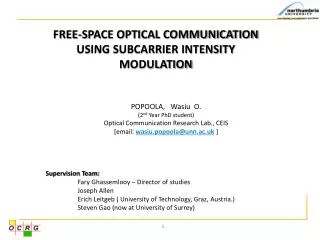
FREE-SPACE OPTICAL COMMUNICATION USING SUBCARRIER INTENSITY MODULATION. POPOOLA, Wasiu O. (2 nd Year PhD student) Optical Communication Research Lab., CEIS [email: wasiu.popoola@unn.ac.uk ]. Supervision Team: Fary Ghassemlooy – Director of studies Joseph Allen

E N D
FREE-SPACE OPTICAL COMMUNICATION USING SUBCARRIER INTENSITY MODULATION POPOOLA, Wasiu O. (2nd Year PhD student) Optical Communication Research Lab., CEIS [email: wasiu.popoola@unn.ac.uk] Supervision Team: Fary Ghassemlooy – Director of studies Joseph Allen Erich Leitgeb ( University of Technology, Graz, Austria.) Steven Gao (now at University of Surrey)
Outline • Problem definition • FSO Introduction • FSO challenges • Subcarrier Intensity Modulation • (with and without diversity) • Results and Discussions • Summary and Future work
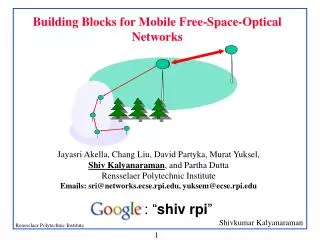
U H H N N REGIONAL FIBRE RING C O METRO FIBRE RING N N B N N H H B Problem Definition FIBRE BASED RING NETWORK RF DOMINATED ACCESS NETWORK 75% of businesses are within one mile of fibre backbone, yet only 5% have access to it - RHK B Business C O Central office H Home U University Building N Network node OPTICAL FIBRE COPPER CABLE
Access Network bottleneck (Source: NTT)
Access network tech. • xDSL: • Copper based (limited bandwidth)- Phone and data combined • Availability, quality and data rate depend on proximity to service provider’s C.O. • Radio link: • Spectrum congestion (license needed to reduce interference) • Security worries (Encryption?) • Lower bandwidth than optical bandwidth • At higher frequency where very high data rate are possible, atmospheric • attenuation(rain)/absorption(Oxygen gas) limits link to ~1km • Cable: • Shared network resulting in quality and security issues. • Low data rate during peak times • FTTx: • Expensive • Right of way required - time consuming • Might contain copper still etc
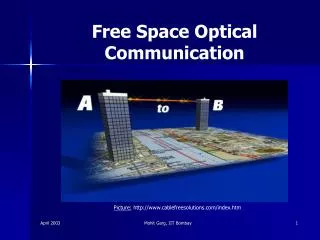
Free- space optical communication What is it? THE USE OF OPTICAL RADIATIONS TO COMMUNICATE BETWEEN TWO POINTS THROUGH UNGUIDED CHANNELS
Unguided channels SPACE WATER (H. Hemmati, NASA) ATMOSPHERE
FSO basics DRIVER CIRCUIT SIGNAL PROCESSING • CLOUD, • RAIN, • SMOKE, • GASES, • TEMPERATURE VARIATIONS • FOG & AEROSOL PHOTO DETECTOR POINT A POINT B Link Range
FSO components FSO Optical (Laser diode) Sources Selected FSO Detectors Germanium only detectors are generally not used in FSO because of their high dark current.
FSO basics The transmission of optical radiation through the atmosphere obeys the Beer-Lamberts’s law which says: Preceive = Ptransmit * exp(-αR) α-- Attenuation coefficient that results from absorption and scattering from the constituents of the atmosphere R – Link Range This equation fundamentally ties FSO to the atmospheric weather conditions
FSO Features • Similar bandwidth/data rate as optical fibre • Very narrow beam – inherent security • No EM interference • No license issues • Cheap (cost about $4/Mbps/Month according to fSONA)
Cost comparison Source:
FSO Features • Fast to deploy (few hours) • Transferable (no sunk cost) • Suffers atmospheric effects most deleterious being thick fog • Strictly line of sight - Pointing, Tracking and Alignment issues FSO can therefore complement/co-exist with all existing access network tech. to guarantee end users improved quality and more services
When did it all start ? 800BC - Fire beacons (ancient Greeks and Romans) 150BC - Smoke signals (American Indians) 1791/92 - Semaphore (French) 1880 - Alexander Graham Bell demonstrated the photophone – 1st FSO (THE GENESIS) 1960s - Invention of laser and optical fibre 1970s - FSO mainly used in secure military applications 1990s to date - Increased research & commercial use due to successful trials (www.scienceclarified.com)
Hospitals Some areas of use In addition to bringing huge bandwidth to businesses /homes FSO also finds applications in : Multi-campus university • Others: • Inter-satellite communication • Disaster recovery • Fibre communication back-up • Video conferencing • Links in difficult terrains • Temporary links e.g. conferences Cellular communication back-haul FSO challenges…
FSO challenges • Major challenges are due to the effects of: • CLOUD, • RAIN, • SMOKE, GASES, • TEMPERATURE VARIATIONS • FOG & AEROSOL DRIVER CIRCUIT SIGNAL PROCESSING PHOTO DETECTOR POINT A POINT B Link Range
FSO challenges Aerosols Smoke Gases
FSO challenges Rain
FSO challenges Fog Fog effect on performance…
Fog effect (H.Willebrand & B.S. Ghuman, 2002.)
FSO challenges Turbulence Others: • Building sway • Background radiation • LOS requirement • Laser safety
The atmosphere behaves like prisms of different sizes and refractive indices Phase and irradiance fluctuation (fading) Atmospheric turbulence CAUSE: Atmospheric random temperature variation along beam path. Incoming optical radiation Eddies of different sizes and refractive indices Depends on: Altitude/Pressure, Wind speed, Temperature and relative beam size.
Turbulence models I : Received irradiance Io: mean irradiance without turbulence σl2 : Log irradiance variance (turbulence strength indicator) Irradiance PDF : Based on modulation concept i.e. Irradiance PDF by Andrews et al (2001): I : Received irradiance Ix: due to large scale effects; obeys Gamma distribution Iy: due to small scale effects; obeys Gamma distribution Kn(.): modified Bessel function of the 2nd kind of order n σl2 : Log irradiance variance (turbulence strength indicator)
Turbulence effect on OOK Using optimal maximum a posteriori (MAP) symbol-by-symbol detection with equiprobable OOK data: OOK threshold level at various turbulence levels OOK based FSO requires adaptive threshold to perform optimally…. Increasing turbulence effect
Turbulence effect on OOK No Intensity Fading Threshold level No Pulse Bit “0” Pulse Bit “1” A/2 A A With Intensity Fading All commercially available systems use OOK with fixed threshold which results in sub-optimal performance in turbulence regimes
Subcarrier modulation The need for adaptive threshold is circumvented through, subcarrier modulation + + - - Standard RF BPSK modulator
Subcarrier modulation TRANSMITTER
Output power m(t) b0 Drive current Subcarrier modulation 5-subcarriers
R = Responsivity P = Average power = Modulation index m(t) = Subcarrier signal Subcarrier modulation RECEIVER
Subcarrier modulation • Performs optimally without adaptive threshold as is the case with optimal OOK • Efficient coherent modulation techniques such as PSK, QAM can be easily used because the bulk of the signal processing is done in RF where matured devices like stable, low phase noise oscillators and selective filters are readily available. • System capacity/throughput can be increased • It outperforms OOK in atmospheric turbulence . • Eliminates the use of equalisers in dispersive channels. • Similar schemes already in use on existing networks But.. • The average transmit power increases as the number of subcarrier increases or suffers from signal clipping. • Intermodulation distortion due to multiple subcarrier impairs its performance
Spatial diversity Diversity Combining Techniques Selection Combining (Sel.C) Equal Gain Combining (EGC) Maximum Ratio Combining (MRC)
Spatial diversity One detector Two detectors Three detectors A typical reduction in intensity fluctuation with spatial diversity Eric Korevaar et. al
Performance metrics System performance analysis is carried out considering the following metrics: 1. Average Bit-Error-Rate (BER) Models the number of bits received in error as a fraction of total transmitted bits SNRe = BPSK subcarrier signal-to-noise ratio p(I) = Irradiance PDF 2. Outage Probability (Po) Measures the probability that the instantaneous BER is greater than a pre-determined/specified threshold level BER*: Threshold BER
Some results Normalised SNR at BER of 10-6 against the number of subcarriers for various turbulence levels (No diversity) Increasing the number of Subcarrier/users, results In increasing SNR Gained SNR Compared with OOK
Some results BER against SNR for M-ary-PSK for log intensity variance = 0.52. (No diversity) BPSK based subcarrier modulation is the most power efficient
Some results Power (dBm) needed to achieve outage probability, Po m (dBm)
Some results The most diversity gain is obtained with up to 4 photodetectors The optimal but complex MRC diversity is marginally superior to the practical EGC Most diversity gain region
Summary • Access bottleneck has been discussed • FSO introduced as a complementary technology • Atmospheric challenges of FSO highlighted • Subcarrier intensity modulated FSO (with and without • spatial diversity) discussed
Progress chat March 2008 Completed On going
Future work • Practical FSO implementation and data analysis • (Joint project with Newcastle University) • FSO with forward error control • SIM average power reduction
Appreciation Academic Staff: Prof. Fary Ghassemlooy ; J.I.H. Joe Allen; Dr. Erich Leitgeb; Dr. Steven Gao; Dr. Krishna Busawon and Dr. Wai Pang. My Colleagues: Wisit, Ming-Feng, Maryam, Sujan , Kamal, Rupak and every member of NCRLab
Acknowledgement I will like to acknowledge Northumbria University for the following awards: ORSA and Research studentship
Thank you. Questions and Comments
FSO availability Availability ranges are based upon two 125/155 Mbit/s FSO transceivers that are located outdoors and transmitting through clear air under normal operating conditions. (Bloom, S. et al. 2003)