Download
1 / 8
80 likes | 96 Views
This comparison analyzes the use of manifolds to reduce mass and arrange pipes into bunches in an end barrel cooling layout. Version 1 charts show the use of manifolds, while Version 2 shows the layout without manifolds. The advantages and disadvantages of each layout are discussed.

E N D
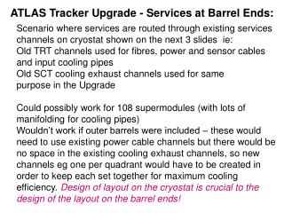
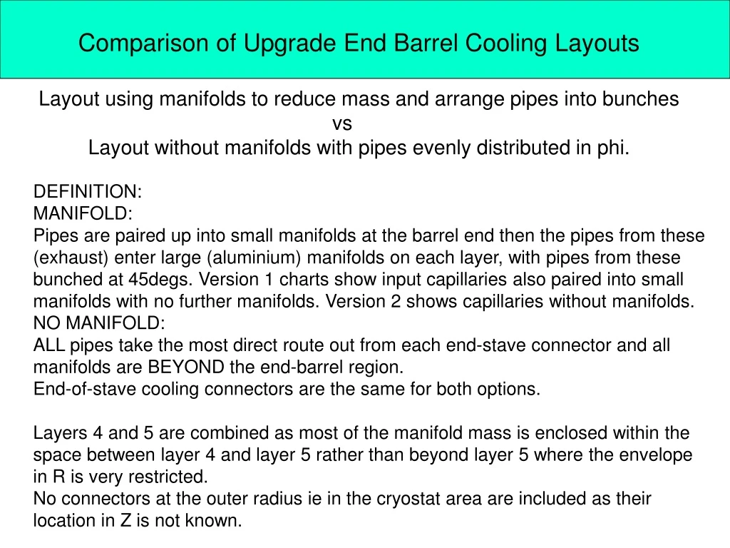
Comparison of Upgrade End Barrel Cooling Layouts Layout using manifolds to reduce mass and arrange pipes into bunches vs Layout without manifolds with pipes evenly distributed in phi. DEFINITION: MANIFOLD: Pipes are paired up into small manifolds at the barrel end then the pipes from these (exhaust) enter large (aluminium) manifolds on each layer, with pipes from these bunched at 45degs. Version 1 charts show input capillaries also paired into small manifolds with no further manifolds. Version 2 shows capillaries without manifolds. NO MANIFOLD: ALL pipes take the most direct route out from each end-stave connector and all manifolds are BEYOND the end-barrel region. End-of-stave cooling connectors are the same for both options. Layers 4 and 5 are combined as most of the manifold mass is enclosed within the space between layer 4 and layer 5 rather than beyond layer 5 where the envelope in R is very restricted. No connectors at the outer radius ie in the cryostat area are included as their location in Z is not known.
LAYER 1 comparison (version 1) tot %Xo/side no manifold manifold
LAYER 2 comparison (version 1) tot %Xo/side no manifold manifold
LAYER 3 comparison (version 1) tot %Xo/side no manifold manifold
LAYERS 4, 5 comparison (version 1) tot Xo/side no manifold manifold
LAYERS 4, 5 comparison - version 2 with no manifolds for capillaries no manifold manifold no manifold for capillaries
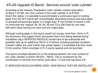
LAYER 4,5 LAYER 1 ID Barrel Upgrade COOLING manifold no manifold 2.131 1.603 manifold 1.615 Total %Xo per side comparison of each layer. no manifold 2.390 no manifold 1.797 manifold 1.399 manifold no manifold LAYER 3 1.817 LAYER 2 1.495 LAYER 1 LAYER 2 SCHEMATIC END BARREL LAYOUT DIVISIONS LAYER 3 LAYER 4,5
CONCLUSIONS Not much difference between cooling with manifolds and cooling without manifolds – if no-manifold pipes can take a direct route on the barrel end. Advantages of layout without manifolds: A more even distribution of mass in phi Fewer connections/welds/bends Easier installation – less danger of damage to other services Easier removal in order to access end of stave region Advantages of layout with manifolds: Fewer (but larger) pipes at high R Fewer connectors (but larger) at cryostat region Disadvantages: Uneven mass distribution over barrel end More chance of stresses on pipes/connectors and probably on end of stave More different components to manufacture Can try other proposed schemes eg Geneva layout – but need dimensions TJF 22/10/08