Download
1 / 11
110 likes | 146 Views
Implement a new cooling scheme to prevent electronics from overheating and failing prematurely. Current plan generates heat from ICs through various components to the cooling fluid. Conduct cooling studies in insulated box with mockup electronics, achieving successful results. Develop a new cooling plan for 100mW, involving thinner lower plate and upper plate sharing cooling tubing. Utilize mockups to show improved design with vertical rail connecting cooling plates. Future steps include prototype testing, FEA calculations to optimize design, and fine-tuning based on results and real electronics data.

E N D
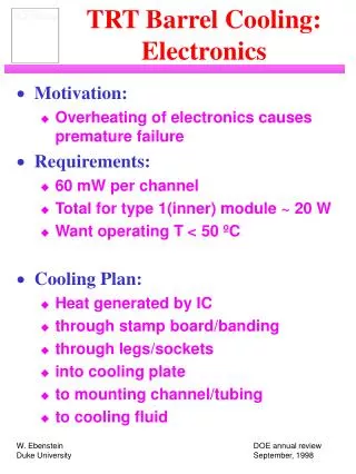
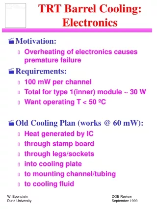
TRT Barrel Cooling: Electronics • Motivation: • Overheating of electronics causes premature failure • Requirements: • 100 mW per channel • Total for type 1(inner) module ~ 30 W • Want operating T < 50 ºC • Old Cooling Plan (works @ 60 mW): • Heat generated by IC • through stamp board • through legs/sockets • into cooling plate • to mounting channel/tubing • to cooling fluid
From Lund: • ASDBLR & DTMROC dummy boards (pictured here) • Roof boards • Readout and display software
1 mm PG cooling plate on type 1 tension plate with Lund mockup electronics (one roof board and two stamp board sets removed)
Results: (60 mW / coolant at 14 ºC) • 1.3 mm Aluminum cooling plate: • ASDBLR: 46.5 ºC • DTMROC: 48.8 ºC • roof boards: 38.8 ºC • cooling, tension plates: ~ 27 ºC • 1.0 mm Aluminum cooling plate: • estimate 4 º higher than above • 1.0 mm PG cooling plate: • ASDBLR: 49.3 ºC • DTMROC: 51.1 ºC • roof boards: 39.5 ºC • cooling, tension plates: ~ 27 ºC • (Typical range: ± 2 ºC) • For 75 mW, add ~9 ºC
New Cooling Plan for 100 mW: • Keep old scheme, and: • Make lower cooling plate thinner • Add upper cooling plate • Plates share cooling tubing • Reasons: • Increase in power expected to come mostly from upper chip (DTMROC) • Too late to make major changes to lower plate design • As always, must minimize material to reduce radiation length
New mockup, showing PG vertical rail connecting cooling plates
New mockup with one roof board removed, showing upper cooling plate
Results: (100 mW - 40/60) • “0.6 mm” Aluminum cooling plates: • ASDBLR: 49 ºC • DTMROC: 50 ºC • roof boards: 28 ºC • cooling, tension plates: ºC
Present Activities: • Proceeding with two-plate prototype: • 0.6 mm thick lower plate • 0.6 mm (at min) upper plate • 3.3 mm wide PG connection from cooling tubing to upper plate, attached with metal-filled epoxy • Proceeding with FEA calculation: • Will model one (or a few) electronics stacks with all cooling parts • Steady state - simplifies problem • Will be able to parameterize plate thickness and material properties to validate and optimize design
Summary: • Two plate design works at 100 mW • Will fine tune dimensions, material choices from: • results of FEA calculations • mockup results with various configurations • measured power consumption of real electronics • changes due to redesign of board-to-board connection (Lund flex design) • changes due to placement of electronics on stamp boards