Download
1 / 42
470 likes | 786 Views
Traffic Signals 101. MnDOT Sample Plan - Jerry Kotzenmacher MnDOT. Without a plan!. Traffic Signal Plans. Why do we need a plan? Building the traffic signal. Bidding Tort Claims Maintenance Locates. Title Sheet - front page. Title Sheet

E N D
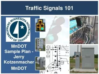
Traffic Signals 101 MnDOT Sample Plan - Jerry Kotzenmacher MnDOT
Traffic Signal Plans • Why do we need a plan? • Building the traffic signal. • Bidding • Tort Claims • Maintenance • Locates
Title Sheet - front page • Title Sheet • The title sheet is required for all traffic signal plans. It includes information such as the title block, project location, governing specifications, etc.
Title Sheet - front page • Governing Specs and Index of Sheets This defines the governing specifications for the project, the project funding and the index of the sheets contained within the plan set.
Title Sheet - front page • Signature Block The Designer should consult with the MnDOT project manager to ensure that the appropriate signature block is used.
Title Sheet - front page • Index Map The index map is used to identify the location of the project(s).
Title Sheet - front page • Standard Plates Summary This identifies the list of Standard Plates that are applicable to this project.
Title Sheet - front page • Plan Symbols & Abbreviations
Title Sheet - page 2 • Quantity Sheet
ALL SHEETS • Title Block The title block is required on all sheets. For the intersection layout sheet the signal system ID, meter address and TE number should be included
Page 3 - Pole Mount Detail • Details
Page 4- APS P. B. Station Details • Details
Page 5 - Equipment Pad Details • Details
Page 6 -Pole Wiring Connector Details • Details
Page 7 - Fiber Optic Schematic Details • Details
Page 8 - Ped Curb Ramp Details • Details
Not part of your plan Details
Page 9 - Signal Layout Signal Face Chart Scale Loop Detector Chart Conduit Wires 4” Conduit 2-12/C/#14 1-6/C#14 2-4/C#14 *1-3/C#14 1/3/C#14 (LUM) 2-2/C#14 *1-3/C#14 1-1/C #6 Ins. Gr Loop Detectors Road Lines conduit Construction Notes Ped diagram and Phasing
Page 9 - Intersection Layout • Typical Controller Phasing Diagram 8 phase NEMA Controller
Controller Operations • Phasing • Dual-ring and Concurrent group Controllers
Match line Match line Page 10 - Signal Layout Pole Notes Advance Detectors
Page 9 & 10 - Intersection Layout • Equipment Pad and SOP Notes Label, in a circle, the controller cabinet or equipment pad “A” and the source of power “B”
Page 9 - Intersection LayoutMast Arm & Pole Symbols Signal Head Indication Signal Head Number Emergency Vehicle Pre-emption Luminaire Mast Arm Signal Pole Base
Page 9 - Intersection LayoutPole Notes • Signal Base Notes The pole note lists the foundation, pole, mast arm and everything that goes on it (signs, heads, hinges, etc) or in it (conductors).
Page 9 - Intersection Layout • Pole 4 Mast arm is 0 degrees Signal Pole Base
Page 9 and 10 - Intersection Layout Pedestrian Signal Face Pedestrian Push Button
Page 9 and 10 - Intersection Layout • Signal Faces Table
Page 9 and 10 - Intersection Layout • Loop Detectors Table
Page 9 and 10 - Intersection Layout • Handhole Labeling Handhole 1 Number handholes clockwise with respect to the controller cabinet with Number 1 being adjacent to or near the controller cabinet. It is not necessary to use H.H. Handhole 17 Handhole 16
Page 11 - Field Wire Diagram Pole 1 Ped station PB2-1 12/c#14 wire Controller cabinet Handhole 14 w/loop Detectors Service cabinet
Page 12 - Field Wire Diagram(2nd Sheet of Wire Diagram) Controller cabinet Cable 58 Heads 5-1 And 2-3 All cables Have numbers Grounded Ins. GR. Cable 58 Ground rod Heads 5-1 And 2-3
Wiring Diagram • Field Wiring
Wire Diagram to LayoutCross reference • page 12 page 9
Wiring Notes • Field Wiring
Interconnect layout - NOT PART OF YOUR PLAN • Traffic Control Interconnect Layout • 1:100 Scale • Include a North Arrow • Include a Scale Graphic • Include General Notes • Clearly Show Guardrail
Other Material Reference • MnDOT Manuals • Signal Design Manual • Roadway Lighting Manual • Signal Timing Manual • Traffic Engineering Manual • MN-MUTCD
It workedwhen I left! • Questions?