Download
1 / 41
540 likes | 1.07k Views
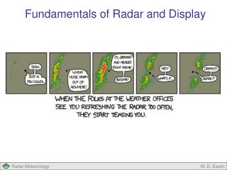
Fundamentals of Radar and Display. Fundamentals of Radar and Display. Outline Radar Components Signal Characteristics Display – NEXRAD Display – Other Types Display – Phenomena. Radar Components. A Typical Pulse Radar System: Four Basic Components Transmitter Antenna Receiver

E N D
Fundamentals of Radar and Display M. D. Eastin
Fundamentals of Radar and Display • Outline • Radar Components • Signal Characteristics • Display – NEXRAD • Display – Other Types • Display – Phenomena M. D. Eastin
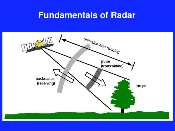
Radar Components • A Typical Pulse Radar System: Four Basic Components • Transmitter • Antenna • Receiver • Display • System is designed to transmit • microwave pulses in shorts bursts • from the antenna, and then activate • the receiver to “listen” for any returns • associated with that pulse • Returns are then amplified and • displayed as radar reflectivity • Duplexer: Switch which allows the • same antenna to transmit • pulses and receive returns M. D. Eastin
Radar Components • A Typical Pulse Radar System: Transmitter • A microwave tube (“Klystron”) produces • pulses of power at a desired frequency • (or wavelength – 10 cm – S-band) • A pulse modulator controls the timing • of each pulse. Typical pulse durations • are ~1 μs with each pulse separated • by a few milliseconds to allow time • for unique returns at large ranges • Pulse Repetition Frequency (PRF) • Sets the timing between each pulse • Fixed (operational radars) • User-controlled (research radars) M. D. Eastin
Radar Components • A Typical Pulse Radar System: Antenna • Output from the antenna is a pulse • modulated microwave-frequency • sine wave. • Waves travel along a microwave • transmission line (or “waveguide”) • through the duplexer to the antenna • The antenna concentrates waves • into the desired shape – often a • narrow cone (or “beam”) for most • meteorological radars • Transmitted beams travel through • the environment until they strike an • object (meteorological or not!) • A very small portion of the beam is • reflected back toward the antenna M. D. Eastin
Radar Components • A Typical Pulse Radar System: Antenna • Sidelobes: • No radar antenna is perfectly built! • Small construction flaws allow for a • portion of the transmitted signal to • escape through “holes” as the beam • is being formed • Can also strike environmental targets • and have power reflected back • Half-power Beam Width • Function of radar design and range • Radius of a conical cross-section • (i.e. a circle) at a given range M. D. Eastin
Radar Components • A Typical Pulse Radar System: Receiver • The echo power is very small compared • the transmitted power • Echoes are first converted to an • “intermediate frequency” by mixing • the unique return echo frequency • with the constant transmitted frequency • Intermediate wave are then amplified • by a known amount before being sent • to the Doppler phase detector and • display unit • Reflectivity: • Amplitude difference between echo • and known amplification • Doppler winds: • Related to frequency difference between • transmitted wave and echo (later…) M. D. Eastin
Signal Characteristics Transmitted Signal: M. D. Eastin
Signal Characteristics Transmitted Signal: Considerations Wavelength: Choice is a function of the target to be studied and budget Larger wavelengths → Precipitation detection Require large antennas ($) Pulse Duration: Choice a function of sensitivity and range resolution Longer durations → Better sensitivity (i.e. less error in a given dBZ) Poorer range resolution (i.e. no detailed structure) PRF: Choice dictates the maximum range at which a target can be detected ( after a pulse has been transmitted, the radar must wait long enough ) ( to allow echoes from the most distant detectable targets to return ) ( “second trip echoes” → Returns observed after the next pulse ) Larger frequencies → Greater range → Multiple echoes of same target (better sensitivity) → Less motion by radar between consecutive pulses (better angular resolution of target) M. D. Eastin
Signal Characteristics Transmitted Signal: Considerations Peak Power: The power of the return echo from a target increases with the transmitted power of the pulse → large peak powers are desired Pulse Energy: Radar sensitivity increases with pulse energy → large magnitudes desired Average Power: Directly related to peak power and pulse energy → large values desired ( Quantity most often calibrated for modern radars ) ( Most radar achieve accuracies of < 0.1 dBz ) M. D. Eastin
Signal Characteristics Transmitted Signal: How to Express Power Ratio of two powers: (decibels) where P1 = Observed power P2 = Reference power (constant) M. D. Eastin
Signal Characteristics Received Signal (Radar Echoes): M. D. Eastin
Signal Characteristics Received Signal (Radar Echoes): Considerations Frequency: Difference between the transmitted and received frequencies is the “Doppler shift” → Proportional to the radial velocity of the target → More on this later… Received Power: Many orders of magnitude smaller than the transmitted power Larger values denote a greater “total” cross-section by the target(s) Minimum Detectable Signal (MDS) → weakest return power that can discriminated from the ever present background noise Time of Arrival: Used to determine target’s range (r) from the radar following: M. D. Eastin
Display - NEXRAD M. D. Eastin
Display - NEXRAD Plan-Position Indicator (PPI) Scanning Strategy: Single Elevation Angle Data collected on a cone are projected onto a plane Echoes close to the radar are at a low elevation Echoes far from the radar are at a high elevation M. D. Eastin
Display - NEXRAD Volume Scanning Strategies: Precipitation mode scan geometry Severe weather scan geometry Saves time…fewer elevations M. D. Eastin
Display - NEXRAD Volume Scanning Strategies: Clear air mode scanning geometry Fewer elevations, slower antenna rotation achieves greater sensitivity for clear air turbulence, clouds, Insects, drizzle, or light snowfall. M. D. Eastin
Display - NEXRAD • Radar Reflectivity: • A measure of the power scattered back to the radar from objects in the path of a radar beam • Proportional to the sum of the sixth power of the diameter of all the particles illuminated by a • pulse provided the particles are smaller than the radar wavelength (more on this later…) M. D. Eastin
Display - NEXRAD • Precipitation Mode: • Used once liquid precipitation • is observed M. D. Eastin
Display - NEXRAD • Clear-Air Mode: • Used for snow and detecting • the onset of deep convection M. D. Eastin
Display - NEXRAD • Base Reflectivity: • Echo intensity at the lowest PPI scan level (0.5°) measured in dBZ M. D. Eastin
Display - NEXRAD • Composite Reflectivity: • Maximum echo intensity at any PPI scan level measured in dBZ M. D. Eastin
Display - NEXRAD • Storm Total Precipitation: • Time integral of base reflectivity after NWS selected start time (measured in inches) • Primary tool to predict flash flooding M. D. Eastin
Display - NEXRAD • Vertically Integrated Liquid (VIL): • Integral of reflectivity (or water mass) through a column (measured in kg /2) • Used to estimate the presence of hail and hail size (large VIL = large hail) M. D. Eastin
Display - NEXRAD • Radial Velocity: • Observed velocity component along the radar beam direction (measured in knots) M. D. Eastin
Display - NEXRAD • Storm-relative Radial Velocity: • Velocity component with the component of the storm motion along the radar beam removed • Best display for detecting mesocyclones, tornado vortex signatures, or microbursts M. D. Eastin
Display - NEXRAD • Combined Radar Reflectivity and Radial Velocity: • Used to detect most severe weather M. D. Eastin
NEXRAD Data • Available Data: • All NEXRAD data since 1992 has been archived and is publically available through the • NCDC at: http://hurricane.ncdc.noaa.gov/pls/plhas/has.dsselect • Level-II: Radar reflectivity and radial velocity at original sampling resolution • Raw volumetric data • Level-III: Derived products most used by forecasters • Base reflectivity • Composite reflectivity • Base radial velocity • Base storm-relative radial velocity • Vertically-integrated liquid (VIL) • Echo tops (ET - maximum height of 10 dBZ echo) • Storm total precipitation • and many more…. M. D. Eastin
Display – Other Types • Range-Height Indicator (RHI) Scanning Strategy: • Radar is scanned in elevation at a fixed azimuth • Volume scans are accomplished by rotating slowly in azimuth while • scanning rapidly in elevation M. D. Eastin
Display – Other Types • Examples of RHI Scans: • Sequence of RHI scans showing • development of shallow cumulus • along the south Florida coast Note ground clutter and echo from tall buildings (echo from radar side lobe) M. D. Eastin
Display – Other Types • Examples of RHI Scans: • Vertical cross-section • through a squall line • reconstructed via • RHI slices through • a PPI volume M. D. Eastin
Display – Other Types • Time-Height Scanning Strategy: • Radar is pointed vertically as storm passes over M. D. Eastin
Display – Other Types • Horizontal cross-sections: • Radar data is interpolated • from cylindrical to Cartesian • coordinates and displayed • in Cartesian space • Often done when constructing • analyses from multiple Doppler • radars (more on this later…) M. D. Eastin
Display – Other Types • Vertical cross-sections: • Radar data is interpolated • from cylindrical to Cartesian • coordinates and displayed • in Cartesian space • Cartesian grid can be sliced • similar to RHI scan • If constructed from multiple • Doppler radars, the vertical • wind component can be • estimated and displayed M. D. Eastin
Display – Other Types • Radar Composites: • Composite reflectivity from multiple PPI scans are projected onto a single display to show • regional or national precipitation distributions • The rain-snow distinction determined by surface observations (not the radar) M. D. Eastin
Display – Phenomena • Beam Blockage: • Caused by tall buildings, trees, water towers, and cell towers near radar… Blocked Beam M. D. Eastin
Display – Phenomena • Non-Meteorological Targets: • Insects and bats often rest during the day and travel at night → take-off at sunset • Birds rest at night and travel during the day → take-off at sunrise Birds departing At 1114 UTC M. D. Eastin
Display – Phenomena • Non-Meteorological Targets: • Ground clutter, aircraft, etc… Ground clutter and diverted aircraft Columbia shuttle Break-up M. D. Eastin
Display – Phenomena • Bright Band: • Enhancement of radar reflectivity at the melting level as large aggregate snowflakes • develop a thin film of water on their surface before they collapse to a smaller drop M. D. Eastin
Display – Phenomena Convective Storms: PPI Displays M. D. Eastin
Fundamentals of Radar and Display • Summary: • Radar Components • Signal Characteristics • Display – NEXRAD • Display – Other Types • Display – Phenomena M. D. Eastin