Download
1 / 5
60 likes | 500 Views
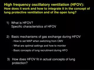
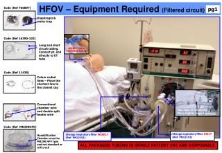
HFOV – Equipment Required (Filtered circuit). Code (Ref 766897). pg1. Diaphragm & water trap. Code (Ref 16390-102). Long and short circuit tubing. Connect pt. end directly to ET tube. DO NOT USE A CATHETER MOUNT. Code (Ref 11438).

E N D
HFOV – Equipment Required(Filtered circuit) Code (Ref 766897) pg1 Diaphragm & water trap Code (Ref 16390-102) Long and short circuit tubing. Connect pt. end directly to ET tube DO NOT USE A CATHETER MOUNT Code (Ref 11438) Colour coded lines – Place the shortest line to the closest cap Conventional chamber wire and double split heater wire Side view of connection Place slightly angled upwards Code (Ref MR290HFV) Change expiratory filter DAILY (Ref PN12152) Change inspiratory filter WEEKLY (Ref PN12151) Humidification Chamber must be MR290 HFV type and not standard or will crack ALL PACKAGED TUBING IS SINGLE PATIENT USE AND DISPOSABLE
HFOV – Machine Set Up Instructions Pg 2 Machine Set Up Instructions Step 1 Gather equipment – diaphragm with water trap, pre packaged long & short tubing (contains caps & inspiratory/expiratory filters), Colour coded lines, Humidification chamber (MR290HFV), conventional long chamber wire, double split heater wire, sterile bag of water & air inlet (pics pg 1) Step 2 Remove the white dome protector, push back the metal dome and attach the diaphragm to the machine (pic opposite). Ensure all diaphragm surfaces are flush with machine. Ensure that the tubing hanging from the bellows hangs in a 6 o’clock position before locking the diaphragm in place. Turn all 4 screws in a clockwise direction to lock. All screws must be in a fully locked position for the machine to operate correctly. Step 3 Place the water trap into the holder that is directly below the diaphragm ensuring the tap is in a horizontal locked position otherwise the system will leak air and lose pressure when operational. Step 4 Place the Humidification chamber on the humidifier (must be MR290 HFV type as a standard chamber will crack) and attach to the sterile water bag. Ensure the chamber fills to its preset filling level. Spike the sterile water with an air inlet. Side view of connection Place slightly angled upwards TURN BELLOWS SCREWS CLOCKWISE TO SECURE Keep Bellows tubing In a 6 o’ clock position N.B. ALL 4 BELLOWS SCREWS MUST BE CORRECTLY SECURED FOR THE OSCILLOTR TO FUNCTION ON/OFF Step 5 Connect the short circuit tubing with its inspiratory viral filter from the humidification chamber to the rear of the machine (Pic opposite) MINIMUM WATER LEVEL (never empty fully or it will lead to a pressure loss) KEEP VALVE IN CLOSED HORIZONTAL POSITION
HFOV – Machine Set Up Instructions (continued) Pg 3 Step 6 Leave the green stopper in the pt end of the long circuit tubing. Attach the widest piece of the tubing to the central connection on the diaphragm -this can be quite stiff to attach (pic opposite). Step 7 Ensure the black angle rest is positioned in a slightly upward position for this section to rest on Step 8 Attach the 2nd widest piece of tubing of the long circuit (has a heater within) to the humidifier chamber. Side view of connection Place slightly angled upwards There are 4 colour coded points directly above the diaphragm. Step 9 Attach the remaining long tubing with the white end from the long circuit tubing to the white pointabove the diaphragm and the remaining short tubing to the top end of the water trap Step 10 Attach the colour coded lines from their points above the diaphragm to the white caps on the circuit tubing. (Shortest line the nearest cap) so green line to the first, red to the next and blue to the cap on the short circuit tubing (pic opposite). Step 11 Connect the machine to the air and oxygen source and connect to mains Step 12 Calibrate the O2 analyser (instructions on side of analyser) Step 13 Switch the machine on (button next to water trap) CARRY OUT A PATIENT CIRCUIT CALIBRATION TEST (described overleaf & on the R side of the machine)
HFOV – Machine Set Up & Calibration Pg 4 Calibration Instructions found on the R side Mean Pressure Monitor Oscillator Mean Pressure Bias Flow KEEP AT 40LPM Amplitude Start at Map +5cm H2o Start at 4cmH20 Alarms RESET/POWER FAIL Start at 33% % Inspiratory time OSCILLATOR START/STOP Ensure LPM rate line Is midway on flow ball Frequency Start at 6 Hz For lung recruitment to pressurise the system hold down reset/power fail button while increasing the mean pressure to a minimum of 10cmH20. Once reached release the reset/powerfail button and increase mean pressure to the therapeutic level (previous conventional MAP + 5cm H2O). Patient Circuit Calibration (Sensormedics 3100B amchine) Before use on a patient, each patient circuit must undergo a patient circuit calibration procedure. Instructions found on the right side of the machine and also( outlined below) Step 1 Complete all set up instructions as described ensuring you leave the green stopper at the patient end of the long tubing until the calibration procedure is completed Step 2 Turn on the Bias Flow Gas to 40LPM ensuring the 40 LPM line is at the middle of the ball Step 3 Set Max PAW Alarm to 59 cmH2O Step 4 Rotate the Mean Pressure(green Dial) and set the control to “Max” Step 4 Adjust the Bias Flow to 20LPM again ensuring that the 20LPM line is at the middle of the ball Step 5 (leave Oscillator Off) Depress and hold Reset/Power Fail and check that the Mean Pressure Monitor display reads 39-43cm H2O. If it does not refer to dept of anaesthetics • Prior to patient commencement (Sensormedics 3100B machine) • Prior to patient connection return the mean pressure adjustment dial to min and increase the bias flow to 40LPM (ensure the 40LPM line is midway on the flow ball) • Set the FiO2 setting to 1.0, the Amplitude to4 cm H2O, the % inspiratory time to 33% and the Frequency to 6Hz • Ensure the following equipment is kept by the patient:1. A conventional ventilator (set up in the bed-space). 2 A self inflating bag (e.g Ambubag - N.B. additional O2 source required) & 3 a green bung (to pressurise the circuit) Follow the units guidelines for steps to be taken prior to HFOV initiation and recruitment strategies for patient commencement (rapid and slow manoeuvres) • The guidelines also cover indications, initial & general management initial settings, weaning and discontinuation
HFOV Machine -- ALARMS Pg 5 PRESET HIGH AND LOW MEAN PRSEEURE AIRWAY ALARMS Upon activation the oscillator will stop and the circuit pressure will vent to ambient. YOU WILL NEED TO RE-RECRUIT HIGH MEAN PRESSURE ALARM Activation of this alarm will trigger the Auto Limit System. The Auto Limit System will open the “blue” limit valve on the circuit and vent pressure. The valve will then re-pressurise to it’s normal operational state unless it pressure reaches Paw>60cmH2O before the issue is resolved. If this happens the circuit pressure will vent to ambient, the oscillator will stop and YOU WILL NEED TO RE-RECRUIT LOW MEAN AIRWAY PRESSURE ALARM Activation of this alarm will only provide audible and visual alarms. The visual alarm will automatically reset after the fault condition has resolved unless the pressure drops to Paw<5cm H20 before the fault is resolved. If this happens the circuit pressure will vent to ambient, the oscillator will stop and YOU WILL NEED TO RE-RECRUIT OSCILLATOR STOPPED ALARM If the oscillatory amplitude is at or below 7 cmH2O and the oscillatory system is pressurised ( the green LED on the start stop button will be lit) both audible and visual indicators will be activated OSCILLATOR OVERHEATED ALARMIf the linear motor temperature exceeds 150 degrees Centigrade this will activate a visual indicator only. SOURCE GAS LOW ALARM If either of the high pressure gas supplies fall below 30 PSI. This will activate the visual indicator only Check gas supply if activated BATTERY LOW ALARM If the nine volt alarm battery needs replaced. this will activate a visual indicator only AFTER RESOLUTION OF THE FAULT THE VISUAL ALARM CAN BE CLEARED BY PRESSING THE RESET/POWER FAIL BUTTON