Download
1 / 14
140 likes | 353 Views
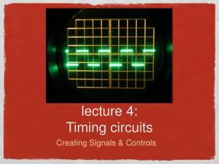
lecture 4: Timing circuits. Creating Signals & Controls. Lecture outline. Reading: 1)Hambley Ch 12.1-12.3 2) Lab 3 handout. Astable Schmitt Multivibrator 555 Timer Monostable 555 Astable 555. 555 Timer. Schmitt trigger. Switches between 2 output rails +/-M.

E N D
lecture 4:Timing circuits • Creating Signals & Controls
Lecture outline Reading: 1)Hambley Ch 12.1-12.3 2) Lab 3 handout • Astable Schmitt Multivibrator • 555 Timer • Monostable 555 • Astable 555 555 Timer
Schmitt trigger • Switches between 2 output rails +/-M. • Switch when inputs equal each other • Use resistors to control this • Inverting and non-inverting Schmitt triggers Inverting Schmitt Standard Schmitt
inverting schmitt with RC chargeup Hambley p.809-812 • This is an astable multivibrator • Negative feedback with RC causes switching • f=1/(2RC ln(3))
Astable multivibrator • start, output high, Vc=0 • RC chargup slowly • When input reaches Vcc/2, • schmitt trigger output low • RC discharges slowly • Cycle repeats forever i.e. astable output
Review-RC circuit charge/discharge • Vc=A+Bexp(-t/RC) • Vc(t=0)=0; boundary condition will be given
555 timer http://en.wikipedia.org/wiki/Flip-flop_%28electronics%29#RS_.28Reset-Set.29_flip-flop • Comparators give signal to flipflop • Flipflop R high, Q low=reset • Flipflop S high, Q high=set
555 monostable Hambley p.818-819 • On-time to be announced by email.
555 monostable • Trigger is high, S is low, RS reset state, Q is low • BJT is on as Q- is high, threshold shunted to ground • When trigger goes low <Vcc/3, RS set Q is high • Q- is low now, BJT off, C charges up thru RA • When threshold reaches 2Vcc/3, RS is reset by top comparator • Everything returns to start state
555 Astable circuit Hambley p.820-821 • Prelab exercise 10kHz and 75% duty cycle Why are trigger and threshold tied together?
555 astable operation • Start with vc=0, so trigger low, RS is set • BJT cutoff, so C chargeup through RA+RB • When threshold reaches 2Vcc/3, RS is set through top comparator, RS is reset, BJT is on • C Discharges thru RB to ground thru BJT • When trigger goes low <Vcc/3, RS sets, cycle repeats
more amplifiers • frequency response cont.