Download
1 / 1
20 likes | 127 Views
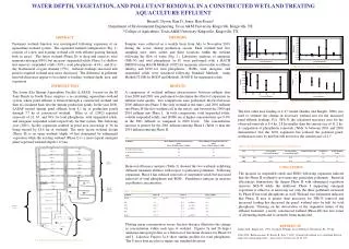
WATER DISTRIBUTION IN CONSTRUCTED WETLAND SOIL PROFILES Bradley J. Petru 1 , Changwoo Ahn 1 , and George Chescheir 2 1 Environmental Science and Policy, George Mason University, Fairfax, Virginia

E N D
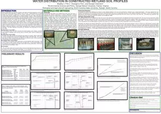
WATER DISTRIBUTION IN CONSTRUCTED WETLAND SOIL PROFILES Bradley J. Petru1, Changwoo Ahn1, and George Chescheir2 1Environmental Science and Policy, George Mason University, Fairfax, Virginia 2Biological and Agricultural Engineering, North Carolina State University, Raleigh, North Carolina INTRODUCTION Wetland habitat types (e.g. forested, emergent, open water) are directly dependent on the long term position of the water table in relation to the root zone. Understanding how soil water storage and movement is affected by the wetland construction process is important for accurate water budget modeling, and for wetland mitigation success. Many site plans for constructed wetlands show predictions of the hydrology (water budgets) for the wetland being built, solely based on the preconstruction physical properties of the soil. However, the wetland construction process can compact the soil, laterally mix adjacent soil types, and vertical integrate soil horizons. Thus the post construction soil properties may not be described accurately in the preconstruction water budget model. If changes in soil properties are not considered in the water budget, there may be a shift in the anticipated hydrologic regime towards site conditions that are either too wet or too dry for the intended wetland habitat. This study in progress compares the soil texture and soil water distribution of soil profiles at two different constructed wetlands to soil profiles representing their respective preconstruction landscape. The water distribution and particle size distribution were determined for the four soil profiles. Available Water Content (AWC) For this wetland study, the AWC represents the plant available water between volumetric water content at saturation (total porosity) and the volumetric water content at wilting point (-15,000 cm). Drainable Water Content (DWC) The DWC is the water drained from a saturated soil profile due to gravity. When a water table is present, drainable water content will change with the depth of the water table. For a given water table, the DWC is represented by the difference in volumetric water content at saturation (total porosity) and the soil water characteristic curve. Non-available Water Content (NAWC) The NAWC is the volumetric water content that is not accessible for plant consumption. This volume of water is held at suction values below the wilting point. The permanent wilting point has commonly been accepted as the water content within the soil profile below -15,000 cm of suction (Richards and Weaver, 1943). HYPOTHESES 1)The soil texture observed in top and bottom horizons at both disturbed study areas are not the same as at their nondisturbed counterparts; 2) The disturbed soil profiles will have a reduced DWC and AWC compared to their nondisturbed counterparts. MATERIALS AND METHODS Particle Size Distribution Soil samples for particle size distribution (see Figure 2) were collected adjacent to the soil cores extracted for volumetric water content determination. Soils were collected from two elevations representing the top and bottom horizons at the undisturbed study areas and at corresponding elevations in their respective disturbed counterparts. A total of ten samples were garnered from each horizon at the Blackjack Study Site and a total of five samples were garnered from each horizon at the Peters Farm Study Site. Soil particle size distribution was determined using the Hydrometer Method as outlined by Gee and Bauder (1986). Study Sites The Blackjack and Peters Farm Wetland Bank study sites (see Figure 1) represent two different approaches to wetland construction commonly implemented within the Culpeper Basin physiographic province of northern Virginia. Located at the crest of a local drainage divide, the design of the Blackjack Wetland Bank uses the existing high clay content of the weathering diabase intrusion to construct multiple large scale, clay-rich basins which capture precipitation and upland runoff. The disturbed study area within the Blackjack Wetland Bank was constructed in the summer of 2007. The Peters Farm Wetland Bank (constructed in summer 2009) is located within the red mudstone hills along the floodplain of a medium sized stream (Owl Run). Small earthen berms and an impervious boundary strategically installed vertically to the bedrock are implemented to raise the local ground water elevation in addition to capturing upland runoff and precipitation. A nondisturbed (pre-grading) and disturbed (post-grading) study area exist at both study sites. Soil Water Characteristic Curves Five undisturbed soil cores were collected from each soil horizon in the disturbed and undisturbed sites at the Blackjack and Peters Farm Study Sites. The soil cores were saturated by raising the water table elevation slowly over the course of one week in a plastic tub. A series of low pressures (see Figure 3) were exerted on these cores, ranging from 0 to -403.6 cm as outlined in Klute (1986). The volume of water removed at each pressure was recorded after the core reached drained to equilibrium conditions. The volumetric water content removed from each soil core at each pressure was averaged together to develop a low suction (0 to -403.6 cm) average soil water characteristic curve for each soil horizon. Additionally, five disturbed soil samples collected from around the undisturbed soil cores were processed for high pressure analysis (-5,000 to -15,000 cm) to determine the volumetric water content held at the wilting point. Gravimetric water content at high pressure ranges (see Figures 4 and 5) were determined using a porous pressure plate apparatus (Cassel and Nielsen, 1986) after each pressure increment was achieved and sustained for several days. The gravimetric water content was then converted to volumetric water content by multiplying the data by the bulk density of the sample. Together, the high pressure and low pressure water release tests provide volumetric water content data that ranges from completely saturated (total porosity) to the wilting point (-15,000 cm). The average soil water characteristic curves were developed from these data. Soil Water Distribution The distribution of soil water within the soil profile for a given water table depth can be estimated using the average soil water characteristic curve data. Assuming drained to equilibrium conditions (the gradient of total head is zero), the tension head is equal to the distance of the surface above the water table, so the water content at a given distance below the surface is equivalent to the pressure head value in the soil water characteristic curve equal to that distance. Components of both soil water characteristic curves representing each individual horizon are pieced together to estimate the soil water distribution for the nondisturbed and disturbed soil profiles at the Blackjack and Peters Farm study sites (see Figures 7, 8, 10, and 11). Calculations of DWC, AWC and NAWC follow Skaggs et al. (1978). The estimations presented below characterize the soil water distribution and the volume drained relationship when the water table has been lowered to the bottom of the “B” soil horizon. The AWC, DWC, and NAWC can be calculated for any water table elevation depth using the soil water characteristic curve and knowledge of soil horizon boundaries. The relationships of the volume drained versus water table depth for the different soil profiles are shown in Figures 12 and 13. PETERS FARM STUDY SITE BLACKJACK STUDY SITE 1 3 4 6 Base map obtained from Google, inc. Figure 1: Location map and aerial imagery of the Blackjack and Peters Farm Wetland Banks. Figure 2: Particle size distribution analysis via the Hydrometer Method (Gee and Bauder, 1986). Figure 3: Soil core samples in preparation for the low pressure measurements (0 to -403.6 cm). Figure 4: Pressure chamber for extreme high suction measurements (-1000 to -15000 cm). Figure 5: Soil samples in preparation for the high suction pressure plate test. • DISCUSSION • The top and bottom horizons of the Disturbed Area at the Blackjack Study Site appear to have the same soil texture as the bottom horizon of the Nondisturbed Area (Table 1). • The top and bottom horizons of the Disturbed Area at the Peters Farm Study Site appear be the same soil texture and are different then either horizon at the Nondisturbed Area (Table 1). • The percentages of AWC and DWC are reduced throughout the entire soil profile at the Disturbed Area of the Blackjack Study Site (Table 2; Figure 7; Figure 8; Figure 12). • The percentage of AWC is reduced throughout the entire soil profile at the Disturbed Area of the Peters Farm Study Site (Table 2; Figure10; Figure 11). • The percentage of DWC has increased throughout the entire soil profile at the Disturbed Area of the Peters Farm Study Site (Table 2; Figure10; Figure 11; Figure 13). • The average Soil Water Characteristic Curves developed for the Blackjack Study Areas (Figure 6; Figure 7; Figure 8) suggest that a large volume of water in clay soils is held by capillary and adsorptive forces above the water table. This soil profile would remain nearly saturated even though the monitoring well shows the soil is drained. • Reducing the DWC volume presents problems with achieving regulatory hydrologic success criteria in mitigation wetlands. • Less water is required to raise or lower the water table in clay-rich soils. This will result in prolonged periods of inundation or drought and a potential in a shift from the desired plant community. • Depending on the soil texture, vertical integration of soil horizons may change the predictive power of the water budget model. PRELIMINARY RESULTS Table 1: Soil texture for the top and bottom soil horizons at the Blackjack and Peters Farm Study Sites. Texture Sand Silt Clay Blackjack Nondist. Top Loam (38.6%) (42.8%) (18.5%) Blackjack Nondist. Bottom Clay (13.0%) (25.3%) (61.7%) Blackjack Disturbed Top Clay Loam (27.4%) (32.6%) (40.0%) Blackjack Disturbed Bottom Clay (15.1%) (21.3%) (63.6%) Peters Farm Nondist.Top Silt Loam (13.1%) (66.7%) (20.2%) Peters Farm Nondist. Bottom Silt Loam (28.7%) (54.0%) (17.2%) Peters Farm Disturbed Top Silty Clay (13.6%) (58.2%) (28.3%) Loam Peters Farm Disturbed Bottom Silty Clay (15.6%) (56.2%) (28.2%) Loam Figure 6: Complete average soil water characteristic curves for the top and bottom soil horizons of the non-disturbed and disturbed study areas at the Blackjack study site. Figure 9: Complete average soil water characteristic curves for the top and bottom soil horizons of the non-disturbed and disturbed study areas at the Peters Farm study site. Figure 12: Predicted water table drainage volumes for the Blackjack Study Site when the water table is lowered to the bottom of the soil profile at the Nondisturbed and Disturbed Areas. Table 2: Changes in AWC, NAWC, and DWC distribution. Data provided in centimeters depth of water and percentage of total water volume for each soil horizon. AWC NAWC DWC Location cm (%) cm (%) cm (%) Blackjack Nondist. Top 4.3 (65.6) 2.2 (34.4) 0.40(6.2) Blackjack Nondist. Bottom 10.6 (31.2) 23.5 (68.8) 0.28(0.8) Blackjack Disturbed Top 2.8 (36.9) 4.8 (63.1) 0.36(4.7) Blackjack Disturbed Bottom 23.8 (40.1) 36.6 (59.9) 0.08(0.1) Peters Farm Nondist.Top 5.5 (58.3) 3.9 (41.7) 1.6(17.0) Peters Farm Nondist. Bottom 10.0 (59.0) 7.0 (41.0) 2.0(11.8) Peters Farm Dist. Top 4.5 (43.8) 5.7 (56.2) 1.8(17.6) Peters Farm Dist. Bottom 15.7 (40.8) 22.8 (59.2) 4.9(12.7) Figure 7: Soil water distribution for the Nondisturbed Area at the Blackjack Study Site when the water table is lowered to the bottom of the soil profile. Figure 10: Soil water distribution for the Nondisturbed Area at the Peters Farm Study Site when the water table is lowered to the bottom of the soil profile. Literature cited Cassel, D.K., Nielsen, D.R. 1986. Field capacity and available water capacity. Methods of Soil Analysis, Part 1: Physical and Mineralogical Methods - Agronomy Monograph No 9 (2nd Ed.). Madison, Wisconsin. 901-926pp. Gee, G.W., Bauder, J.W. 1986. Particle-size Analysis. Methods of Soil Analysis, Part 1: Physical and Mineralogical Methods - Agronomy Monograph No 9 (2nd Ed.). Madison, Wisconsin. 383-411pp. Klute, A. 1986. Water retention: laboratory methods. Methods of Soil Analysis, Part 1: Physical and Mineralogical Methods - Agronomy Monograph No 9 (2nd Ed.). Madison, Wisconsin. 635-662pp. Skaggs, R.W., Wells, L.G., Ghate, B.R. 1978. Predicted and measured drainable porosities for field soils. Transactions of the ASAE. 21(3):522-528. Richards, L.A., Weaver, L.R. 1943. Fifteen-atmosphere percentages as related to the permanent wilting percentage. Soil Science. 56:331-339.. Figure 13: Predicted water table drainage volumes for the Peters Farm Study Site when the water table is lowered to the bottom of the soil profile at the Nondisturbed and Disturbed Areas. Figure 8: Soil water distribution for the Disturbed Area at the Blackjack Study Site when the water table is lowered to the bottom of the soil profile. Figure 11: Soil water distribution for the Disturbed Area at the Peters Farm Study Site when the water table is lowered to the bottom of the soil profile. Acknowledgments The authors thank Angler Environmental for site access and logistical support. Additional funding was granted from the Piedmont Wetlands Research Program.