Power Triangle
Learn about power components, triangles, reactive power, impedance, and line currents in three-phase systems. Phasor diagrams show electrical relationships in delta and wye configurations.

Power Triangle
E N D
Presentation Transcript
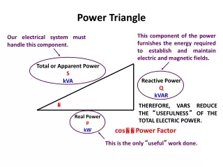
This component of the power furnishes the energy required to establish and maintain electric and magnetic fields. Our electrical system must handle this component. This is the only “useful” work done. Power Triangle Total or Apparent Power S kVA Reactive Power Q kVAR THEREFORE, VARS REDUCE THE “USEFULNESS” OF THE TOTAL ELECTRIC POWER. Real Power P kW cos Power Factor
Power Triangle Power triangle in first quadrant (positive ) indicates INDUCTIVE load.
Power Triangle Power triangle in fourth quadrant (negative ) indicates CAPACITIVE load.
Power Triangle Z S X Q R R = resistance X = reactance Z = impedance P Power triangle and impedance triangle are SIMILAR TRIANGLES.
Three-Phase Systems Three-phase systems Most common: 3-wire delta and 4-wire wye Mathematical representation Time domain (oscilloscope view) Frequency domain (phasor diagram)
Three-Phase Systems Delta-connected loads Line-to-line voltage only No neutral, so best for balanced loads Ideal for motors Wye-connected loads Line-to-line AND line-to-neutral voltage Better for imbalanced loads, particularly mix of three-phase and single-phase
Unbalanced Delta Load A three-phase, three-wire, 240-volt system with A-B-C phase sequencing supplies a delta-connected load as shown below. Determine the line currents and draw the phasor diagram.
ICA 240 /120 VAB IAB = = = 24 /120 ZAB 10 /0 IAB IBC 240 /0 VBC IBC = = = 24 /330 ZBC 10 /30 240 /240 VCA ICA = = = 16 /270 ZCA 15 /–30 Unbalanced Delta Load A three-phase, three-wire, 240-volt system with A-B-C phase sequencing supplies a delta-connected load as shown below. Determine the line currents and draw the phasor diagram.
ICA IAB IBC Unbalanced Delta Load A three-phase, three-wire, 240-volt system with A-B-C phase sequencing supplies a delta-connected load as shown below. Determine the line currents and draw the phasor diagram. IAB = 24 /120 IBC = 24 /330 ICA = 16 /270 IA = IAB – ICA = 24 /120 – 16 /270 =38.69 /108 IB = IBC – IAB = 24 /330 – 24 /120 =46.37 /315 IC = ICA – IBC = 16 /270 – 24 /330 =21.17 /191
Unbalanced Delta Load A three-phase, three-wire, 240-volt system with A-B-C phase sequencing supplies a delta-connected load as shown below. Determine the line currents and draw the phasor diagram. VAB = 240 /120 IA = 38.69 /108 VBC = 240 /0 IB = 46.37 /315 VCA = 240 /240 IC = 21.17 /191
Unbalanced 4-Wire Wye Load A three-phase, four-wire, 208-volt system with A-C-B phase sequencing supplies a wye-connected load as shown below. Determine the line currents, the neutral current, and draw the phasor diagram.
VAN 120 /270 IA = = =20 /270 6 /0 ZAN VBN 120 /30 IB = = =20 /0 6 /30 ZBN VCN 120 /150 IC = = = 24 /105 5 /45 ZCN Unbalanced 4-Wire Wye Load A three-phase, four-wire, 208-volt system with A-C-B phase sequencing supplies a wye-connected load as shown below. Determine the line currents, the neutral current, and draw the phasor diagram. IN = –(IA + IB + IC) = 14.15 / 193
Unbalanced 4-Wire Wye Load A three-phase, four-wire, 208-volt system with A-C-B phase sequencing supplies a wye-connected load as shown below. Determine the line currents, the neutral current, and draw the phasor diagram. IA = 20 /270 VAN = 120 /270 IB = 20 /0 VBN = 120 /30 IC = 24 /105 VCN = 120 /150 IN = 14.15 / 193