
Accelerator System - Vacuum
E N D
Presentation Transcript
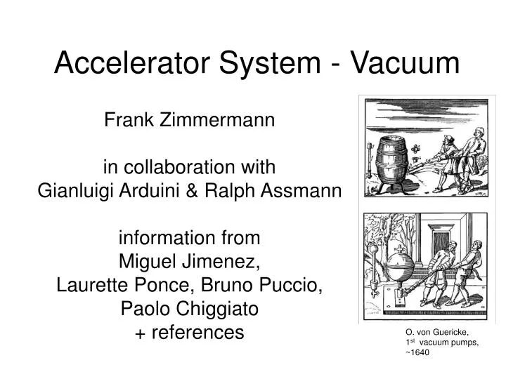
Accelerator System - Vacuum Frank Zimmermann in collaboration with Gianluigi Arduini & Ralph Assmann information from Miguel Jimenez, Laurette Ponce, Bruno Puccio, Paolo Chiggiato + references O. von Guericke, 1st vacuum pumps, ~1640
topics • requirements; LHC vacuum system; P measurements • signals available in the control room: beam vacuum, insulation vacuum, sampling rate • bake-out and NEG activation • 450-GeV vacuum pressure and beam lifetime • collimation vacuum • e-cloud test bench • effect of quench on beam and insulation vacuum • beam operation at 450 GeV; beam measurements • higher intensity and 7 TeV • He leaks
vacuum requirements & effects on beam design pressure corresponds to ~100 h beam lifetime due to nuclear interaction with residual gas; or to an average loss rate of 6x10⁴ p/m/s (quench limit at 7 TeV: 8x10⁶ p/m/s; at 450 GeV: 7x10⁸ p/m/s); at 450 GeV the design gas pressure yields an emittance doubling time between 30 and 10 h depending on species, due to multiple Coulomb scattering
LHC vacuum system Sectors separated by valves Experimental IRs: cold sectors - triplet, Q4, Q5, Q6, arc (2900 m!) warm sectors – intermediate regions, and space around IP IR7: 3.5 vacuum sectors between IP and arc IP triplet D2,Q4 Q5 Q6 arc IP7
pressure measurements - gauges Penning gauge: more stable, less precise cold-cathode gauge 2 electrodes: anode, cathode + permanent magnetic field invented 1937 by Penning precursor of sputter-ion pump nonlinear dependence Bayard-Alpert gauge: less stable, more precise hot-cathode gauge, 3 electrodes: filament, collector, grid invented 1950, revolution in vacuum technology linear dependence, ultra-low vacuum
pressure measurements – locations Beam vacuum: Cold parts: Penning gauge (in attached short RT section) Warm parts: both types of gauges At least two Penning gauges per vacuum sector (warm or cold); 6-8 gauges / arc (every 3 or 4 cells) 1 B-A gauge per warm vacuum sector Insulation vacuum: Penning gauge with autoprotect (OFF for pressure >5e-5 torr) Penning gauge cold 20 cm no simple rule to deduce actual pressure in cold part!!
LSS schematic view, courtesy M. Jimenez
Point 8 27 March vacuum valve Pirani gauges Penning gauges
signals available in the control room all pressure gauge readings at sampling rate 0.1 Hz (locally increased during MD periods to 1 Hz) available through vacuum PVSS interface vacuum alarms naming convention?
signals available in the control room – 6 Penning gauge (VGP) located in a combined vacuum sector (.C instead of .R or .B for red and blue beams), in vacuum sector B5R8. The 39 means that the gauge is located at a distance of 39 m from the sector valve when leaving the IP.
vacuum interlock User_Permit Beam_Permit Vacuum BIS LBDS Beam_Info • Vacuum User_Permit = “FALSE” if: • Valves open or move • Pressure over threshold • If default: Vacuum changes its User_Permit from “TRUE to “FALSE” • The BIS changes the Beam_Permit from “TRUE to “FALSE” => beam is extracted by LBDS • The BIS changes Beam_Info signal from “TRUE to “FALSE” • NO beam => (if needed) Vacuum could close the sector valves (L. Ponce, B. Puccio, MPSWG, 14.02.207)
plans for bake-out and NEG activation present plan: all RT parts will be baked only question concerns the ceramic chambers MKD in IR6 L&R (2 x 22 m); due to scheduling conflicts, this was being discussed with Brennan
collimation vacuum total outgassing rate of collimators ~2x10⁻⁷ mbar l/s pumping speed ~20 l/s → pressure < 10-8 mbar + pressure will decrease by factor 10 in ~1 year pressure spike due to beam loss if pressure >5x10⁻⁵ mbar: valves close press. jaw T1>T0: thermal stimulated desorption jaw T0 decay time determined by pumping speed time
electron-cloud test bench postponed to 2008-09 shutdown
effect of quench on beam & insulation vacuum depends on temperature transient of the cold bore peak temperature < 30 K: small effect, release of H2 peak temperature > 30 K: release of CO, CH4 temp. >30 K? time
quench effect in String 2 Test LHC Project Report 681; V. Baglin, Chamonix XIII
beam operation & beam measurements no pressure change expected for 450-GeV commissioning beams no special beam measurements needed of course, vacuum group will monitor pressure readings
pressure evolution in the 1st year V. Baglin, Chamonix XII
2008: higher intensity and 7 TeV synchrotron-radiation photons heating induced by secondary halo or nuclear cascade behind the collimators
helium leaks in cold arcs localized He leak can cause quenches - but is likely not visible in beam lifetime or emittance; e.g., 10-m long He bump with local proton loss rate of 8x10⁶/m/s (= quench limit at 7 TeV) reduces beam lifetime from 100 to 99 hr & emittance growth time at 450 GeV/c from 14.2068 hr to 14.2064 hr. helium front propagates slowly (few cm/hr) - only after weeks or months it arrives at closest pressure gauges (placed every 300-400 m); standard beam-loss monitoring system (every 53 m) may be unable to detect & localize leak; 1) solution: deploy mobile “BLM snake” with 2-m BLM spacing (B. Jeanneret) 2) alternative solution (A. Poncet, CERN MT/95-01 (ESH)): debunch beam @ 450GeV & measure e- ionization current 3) on-line measurement of heat load to cryogenics (V. Baglin, Chamonix XIV)
conclusions many readings available nothing special expected for 450 GeV commissioning lifetime ok at higher intensity & 7 TeV: higher steady-state pressure in regions behind collimators sudden beam loss on collimators could cause pressure spike which leads to valve closure desorption from SR photons
references O. Gröbner, 'Technological Problems related to the Cold Vacuum System of the LHC'', Vacuum, vol. 47, pp. 591-595 (1996). 2) LHC Design Report, Vol. I, Chapter 12: Vacuum System 3) V. Baglin, Running In – commissioning with Beam, Chamonix XII. 4) V. Baglin, Vacuum Transients During LHC Operation, Chamonix XIII. 5) V. Baglin, How to Deal with Leaks in the LHC Beam Vacuum, Chamonix XIV. 6) A.Poncet, Pressure Measurements and Helium Leak Detection in the LHC Cold Bore using the Electron Current from Ionization of the Gas by the Proton Beam, CERN MT/95-01 (ESH) (1995). 7) L. Ponce, B. Puccio, MPS aspects - Commissioning of the Vacuum System, MPSWG, 14 February 2007. 8) E. Blanco et al, Experimental Validation and Operation of the LHC Test String 2 Cryogenic System, LHC Project Report 681 (2004). 9) J.M. Jimenez, Electron Cloud Diagnostics in the LHC, EDMS document LHC-VI-EC-0001 v.1.0 (2003). 10) Tour of LHC Point 8, 27 March 2007. 11) Discussion with M. Jimenez, 1 February 2007.