Download

1 / 8
90 likes | 234 Views
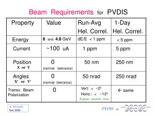
BEAM PHASE DETECTOR – PILLBOX CAVITY Basic Requirements and Parameters Operating frequency: S-Band: f = 2856 MHz Loaded cavity bandwidth: 500 kHz Q o 2856/0.5 = 5700 Power extracted from the cavity: 0.5 – 1 W Phase resolution: 0.03 Charge of a single bunch: 0.1 – 1 nC

E N D
BEAM PHASE DETECTOR – PILLBOX CAVITY • Basic Requirements and Parameters • Operating frequency: S-Band: f = 2856 MHz • Loaded cavity bandwidth: 500 kHz Qo 2856/0.5 = 5700 • Power extracted from the cavity: 0.5 – 1 W • Phase resolution: 0.03 • Charge of a single bunch: 0.1 – 1 nC • Beam velocity, (v/c): = 1.0 • Axial space available: ~4” (~10 cm) • Bore of the beam pipe: 0.87” i.e. r = 1.105 cm • Superfish Simulation – 1” cavity See Fig1 and Table 1. • Cavity diameter: 3.27” • Cavity height: 1.0” • Unloaded Quality factor: Q = 12800 • Cavity Shunt Impedance R = V2p/2P = 1.5 M • Transit Time Factor: T = 0.798 • Wake-loss parameter: k = 6.76x10¹¹ V/C Vojtech Pacak/Ron Akre
Calculated Secondary Parameters – all values for a bunch charge 1 nC • Voltage induced in the cavity by a relativistic charge q: Vq = 2 k.q ----------1352 Vp • Energy stored in the cavity: Wq = (Vq/2) q ------ 6.76 x 10⁻⁷ J • Power lost in the cavity: P = Wq/Q --------- 0.95 W • Peak voltage generated into 50 load for = 1, (Qe = Q): V50 = √(2x50xP) --9.7 Vp Note:1) for a bunch charge 0.1 nC the deposited energy will be 100 times smaller and the induced voltage will be 10 times smaller 2) the above results were calculated for a critically coupled cavity; the output signal will depend on the output coupling coefficient , i.e. on the external Qe, see the graphs on Figs. 2 -5. 3) real cavity shunt impedance R will be 10 – 20% smaller Vojtech Pacak/Ron Akre
Phase Signal Losses • 14-bit ADC max signal: full scale output: 2.3 Vp-p or ~11 dBm • Mixer Loss: 6 dB • Chassis Losses: 2 dB • Cable Losses: 8 dB ______________ Signal power needed for full scale ADC output: ~27 dBm or 0.5 W • S/N Ratio • ADC S/N Ratio: ~70 dB, (noise level ~ 260 V rms) Available cavity output power and Vrms and S/N ratio at the ADC input for critical coupling: 1 nC bunch: ~1.0 W , ~1.1 Vrms , ~72 dB 0.1nC bunch: ~0.01 W , ~0.1 Vrms , ~52 dB The above S/N ratio can further be increased by ~14 dB, (i.e. by a factor of 5), by averaging the output signal from the cavity – see Fig. 6. • Phase Resolution 0.1nC bunch, S/N ratio after averaging 64 samples: 66 dB • Phase signal resolution = 10-66/20 = 5 x 10 -4 radian ~= 0.03. • Pillbox Cavity Test Model • Simple mechanical model of the cavity is currently under construction, see Fig. 7. Vojtech Pacak/Ron Akre
Fig. 1 1” pillbox cavity Axial Electric Field = 1000 V/m r [cm] 79 V 90 V z [cm] Vojtech Pacak/Ron Akre
TABLE 1 2.856-GHz TM010 Short Pillbox Cavity Full, 1 inch Problem file: C:\LANL\MY_FILES\LCLS_PHASEDETECTOR CAVITY\PH_DET_CAV_INCH_LCLS_FULL_BEAM_PIPE4_5CM.AF 7-23-2005 10:48:38 ------------------------------------------------------------------------------- Field normalization (NORM = 0): EZERO = 0.00100 MV/m Frequency = 2854.19710 MHz Relation between RF definition of the shunt impedance Beta = 1.0000000 and the effective "linac shunt impedance definition”: Transit-time factor = 0.7981844 R/Q = (r/Q)/(2T2) Stored energy = 1.90824E-09 Joules Using standard room-temperature copper. Data used for calculation Surface resistance = 13.93808 milliOhm Normal-conductor resistivity = 1.72410 microOhm-cm Operating temperature = 20.0000 C Power dissipation = 2673.3028 uW Q = 1.2801E+04 Shunt impedance = 3.3666E+01 MOhm/m Rs*Q = 178.424 Ohm Z*T*T = 2.1449E+01 MOhm/m r/Q = 150.797 Ohm Wake loss parameter = 0.67608 V/pC Wall segments: Segment Zend Rend Emax Power P/A dF/dZ dF/dR (cm) (cm) (MV/m) (uW) (uW/cm^2) (MHz/mm) (MHz/mm) ---------------------------------------------------------------------------------------------- 3 -1.3000 1.1050 6.3341E-03 2.050 9.23E-02 0.000 5.237 4 -1.3000 4.0950 6.3279E-03 800.5 16.39 -3.041 0.000 5 1.3000 4.0950 3.3699E-07 1068. 15.97 0.000 -72.03 6 1.3000 1.1050 6.7441E-03 800.5 16.39 -3.041 0.000 7 4.5000 1.1050 6.7441E-03 2.077 9.35E-02 0.000 5.242 ---------------------------------------------------------------------------------------------- Total Dissipated Power 2673. Vojtech Pacak/Ron Akre
Figs. 2 - 5 Vojtech Pacak/Ron Akre
FIG. 6 Vojtech Pacak/Ron Akre
FIG. 7 Vojtech Pacak/Ron Akre