Understanding Extrusion Chapter 5
Understanding Extrusion Chapter 5. Professor Joe Greene CSU, CHICO. MFGT 144. Chap 5: How an Extruder Works. Solids Conveying Gravity Induced Conveying Drag Induced Conveying Starve Feeding Grooved Feed Extruders Melting Contiguous Solids Melting Dispersed Solids Melting

Understanding Extrusion Chapter 5
E N D
Presentation Transcript
Understanding ExtrusionChapter 5 Professor Joe Greene CSU, CHICO MFGT 144
Chap 5: How an Extruder Works • Solids Conveying • Gravity Induced Conveying • Drag Induced Conveying • Starve Feeding • Grooved Feed Extruders • Melting • Contiguous Solids Melting • Dispersed Solids Melting • Melt Conveying • Melt Temperature • Mixing • Degassing • Die Forming
Solids Conveying • Gravity Induced Conveying: Material flows down the feed hopper into the feed throat and from there into the screw channel • Important Bulk properties • Bulk density- density of material including air voids • Compressibility- change in bulk density when pressure is applied • Internal coefficient of friction- between the plastic particles • External coefficient of friction- between plastic and hopper • Particle size and distribution- PCR material are difficult to handle due to large particle size distribution • Design of feed hopper effects flow in hopper to prevent stagnation and bridging • Circular hopper is better than square hopper (Fig 5.1) • Crammer feeder can be used for PCR materials • Diamondback feed hopper has a circular cross section to a oval cross section to a circular cross section. (Fig 5.4)
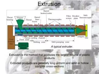
Solids Conveying • Drag Induced Conveying Fig 5.5 • Plastic moves forward from rotation of screw due to friction with the barrel wall and not the friction with the screw. • Analogy is a nut on a screw. If the nut is free to rotate it will not move up the screw. If the nut is held the nut moves forward. • Starve Feeding (Fig 6.5) • Method of feeding the extruder where the plastic is metered into the extruder at a rate below the flood feed rate. • The screw channel is partially empty in the first few diameters of the extruder. • Results in very little pressure buildup in the plastic and as a result very little frictional heating and mixing. • Effectively reduces the length of the extruder, e.g. a 25:1 L/D extruder may have an effective length of 21 L/D with the first 4 diameters partial • Used on high speed twin screw extruders. • Reduces motor load, melt temperature, and useful when adding several ingredients simultaneously through one feed port from several feeders.
Solids Conveying • Grooved Feed Extruders (Fig 5.6) • Driving force for the conveying process is the frictional force at the barrel surface. • Grooves effectively increase the barrel temperature. • Grooves typically run in the axial direction with the length of several screw diameters. • Advantages of grooved feed extruders (Fig 5.7) • Output is less dependent on pressure resulting in increased stability • Output tends to be higher than that of smooth bore extruders • Allows extrusion of very high molecular weight plastics, HMWPE • Disadvantages • Grooved barrel section has to be cooled well enough to avoid premature melting of plastic in the grooves reducing energy efficiency and adds to complexity of extruder • Stresses can be high in groove causing them to wear • Pressure required can be high, thus need strong barrel
How an Extruder Works • Conventional extruders without grooved barrel sections can be modified to include grooves • Modify the feed throat with a grooved liner (fig 5.6) • Most extruder stability problems occur in solids conveying section • Grooved feed throat can improve extruder performance • Improve barrel friction or reduce screw friction • Affected by screw design, screw temp, and screw material • Screw design features that reduce screw friction (Fig. 5.8) • Single flighted geometry (avoid multiple flights) • Large flight flank radius • Large Helix angle
How an Extruder Works • Reduce screw friction • Internal screw heating • Coring the screw and circulating heat transfer fluid • Cartridge heater inside the screw • Apply a coating to the screw or a surface treatment. • PTFE impregnated nickel plating • PTFE/chrome plating • Titanium-nitride • Boron-nitride • Tungsten-disulfide (WS2) • Catalytic surface conversion (J-Tex) • Advantage of a low friction coating • Improves conveying along screw • Reduces tendency of plastic to build up on screw surface, is easier to clean • Coatings can be used for extrusion dies which reduce pressure drop • Reduces tendency for material to build up at exit or dye drool
Melting • Contiguous Solids Melting (Fig 5.9) (CSM) • Solid particles are compacted and form a solid plug that spirals along the length of the screw channel. • Thin film of plastic is located between solid bed and barrel • Most of the melting occurs at the interface between two • Newly melted material collects in the melt film then is dragged away • Most often observed in single screw extruders • Dispersed Solids Melting (Fig 5.10) (DSM) • Solid particles are dispersed in a melt matrix, decrease in size till melted • Observed in high-speed twin extruders and reciprocating single screw compounding extruders. • Melting is more efficient than Contiguous solids melting (CSM) • Length to achieve melting in the axial direction is 1 to 2 screw Diameter • Versus single screw extruders length is 10 to 15 diameters • Versus twin screw extruders length is 5 to 6 diameters • Important when have a 25L/D extruder that won’t have length for melt conveying, mixing or degassing. • Twin screw is more versatile than single screw
CSM Melting • CSM Theory developed by Tadmor • Determine how plastic properties, processing conditions and screw geometry affect melting • Two sources of heat • Barrel heat conducts from heaters through barrel and to melt • Viscous heating caused by viscous movement of melt • Drag induced melt removal • Melted material is dragged away by rotation of screw • Thin melt film is essential to proper melting • Single screw extruders melt more efficiently than ram extruders • Similar to a stick of butter melting in frying pan; best if moved around • Thin melt film is essential parameter to high melting efficiency • Melt thickness determined from flight clearance. Larger flight clearance results in thicker melt film. • Important to keep flight clearance small • Increase in barrel temperature causes increased heating of plastic • causing viscosity to drop causing viscous dissipation to drop and less efficient melting. Thus, increase in barrel temp can reduce melting efficiency
CSM Melting • Helix angle can have considerable effect on melting • Helix angle increases, melting efficiency increases Fig 5.11 • Highest melting efficiency (shorter length) is with 90º • Such angle not good for conveying since 90º means that screw flight is parallel to the axis of screw and conveying capability is zero. • Good range for helix angle is between 20º to 30º • Multiple flights can also improve melting (Fig 5.12) • Melt film is thinner than in a single flighted screw (Fig 5.13) • Drawback is that it reduces solids conveying and melt conveying. • Use multiple flights if extrusion is limited by melt capacity
Barrier Screw • Barrier screw has two flights: main and barrier • Main flight: is to separate the solid material from melted • Barrier flight (Fig 5.14) separates solid bed from the melt pool. • Barrier screw melting capability is same as a single flighted screw without a barrier flight.
Barrier Screw • Advantages • Achieves more stable extrusion than simple conveying • No chance of unmelted material being beyond barrier section • Certain amount of dispersive mixing occurs as plastic flows over barrier into melt channel. • Disadvantages • No better performers than screws with mixing sections • More expensive than non-barrier screws • More susceptible to plugging due to solid material restricted to the solids channel. • Melting can not keep up with reduction in the size of the channel in compression section of the screw, resulting in the solid material getting stuck in the screw channel. • Creates a momentary obstruction to flow and leads to surging or variation in extruder output
Melt Conveying • Melt Conveying starts when melting is completed • Melt conveying zone is region where all plastic is melted • Mechanism for melt conveying is viscous drag • Viscous force at the barrel is responsible for conveying • Viscous force at the screw is responsible for retarding force • Melt conveying is improved by reducing barrel temperature and increasing screw temperature • Optimum screw geometry for conveying • Optimum helix angle is dependent on degree of non_Newtonian behavior of plastic melt, n (power-law index, which is slope of log viscosity-log shear rate) • Optimum helix angle for melt conveying decreases as power law index decreases; in other words, when the plastic is more shear thinning • Optimum depth depends upon: • Viscosity, pressure gradient, and power law index • When plastic becomes more shear thinning, the channel depth should be reduced to obtain good melt conveying
Melt Temperature • Temperatures vary considerably in melt conveying • Due to low thermal conductivity • Local temperatures are difficult to measure due to screw • Numerical techniques can predict temperatures with finite element analysis with flow and pressures (Fig 5.15) • Hottest near center of channel and coolest at screw • Temperature distribution due to curling flow pattern • (Fig 5.16) • Fluid close to barrel surface flows in direction of channel • Recircualting flow (Fig 5.17) causes inner layer is trapped • Outer layer insulates inner hot layer • Important to keep non-uniform heating layers away from end of screw with mixing sections in design of screw to achieve thermally homogeneous.
Distributed Mixing • Takes place in melting and melt conveying zones • Due to plug flow behavior, little mixing occurs in solids conveying. Waits until all plastic is melted • Distributed Mixing • Extent determined from total shear deformation of plastic melt • Total shear deformation = shear rate · length of time exposed to shear rate . Where, shear rate is found from velocity/distance and length of time is Volume/flow rate • Example, plastic melt is exposed to shear rate of 100 sec–1 for 15 seconds the resulting strain is 1,500. (Dimensionless) • Mixing is determined by velocity in 2 directions Fig 5.18 • Direction of channel (z-direction velocity is vz) • Direction across channel (x-direction velocity is vx) • The third direction, parallel to flight flank is usually small, vy.
Distributed Mixing • Down channel velocities (vz) depend upon Pressure gradient • Positive: pressure is increasing along melt conveying zone • Negative: pressure is decreasing along melt conveying zone • Fig 5.19 • Cross Channel flow • At top of channel, material flows to the left by drag flow • At bottom of channel, material flows to the right by pressure flow • Fig 5.20 • Shear rate • Determined from the slope of the velocity profile (velocity versus position) • Slope of velocity profile is also called velocity gradient • Fig 5.21 • Pressure affects on shear rate • Press gradient is positive then the shear rates increase toward the barrel surface • Press gradient is zero then the shear rates is constant • Press gradient is negative then the shear rates decrease toward the barrel surface • Cross channel shear rates can be determined in the same way. • Fig 5.22
Shear Rate • Channel flow is helical (Fig 5.23) • If unroll screw channel onto flat plane material follows helical path • At top, the fluid element travels in the direction of the barrel • At bottom, the fluid elements travel across the channel. • Resident time is the length of time the material spends in the channel • Dependent on velocities and geometry of channel (Volume of channel/ Volumetric flow rate) • Resident time as function of distance: Fig 5.24 • Fluid elements at center have shortest resident time • Residence time increases toward the screw and barrel surfaces • Residence time is very long at barrel and screw surfaces • Outer Region A and inner region B (Fig 5.25)
Cross Channel Shear Strain • Total cross channel shear strain can be determined • adding the shear strain of the upper portion to that of the lower portion of the channel • Fig 5.26: • Total shear strain vs. normal distance (thickness) at several throttle ratios (pressure flow to drag flow: rd=0 pressure flow or rd = 0.333 then drag flow is 3 times pressure_ common) • Elements close to barrel wall experience high strain and mixing • Mixing in center increases with increasing rd by increasing resistance at end to flow by adding screen packs
Mixing • Best way to improve mixing in single screw extruders is to incorporate mixing sections • Desirable characteristics for mixing section • Minimum pressure drop with forward pumping capability • Streamlined flow and no deadspots • Barrel surface wiped completely with no circumferential grooves. • Operator friendly and easy to install, run, clean, etc. • Easy to manufacture and reasonably priced.
Distributive Mixing Sections • Specific characteristics for distributive mixing • Plastic melt subjected to significant shear strain • Flow should be split frequently with reorientation of melt • Types • Cavity mixers • Pin mixers • Slotted flight mixers • Variable channel depth mixers • Variable channel width mixers
Cavity Mixers • Cavity transfer mixer (CTM) • Consists of screw section and barrel section. Both containing hemi-spherical cavities (Fig 5.27) • Advantages • Good mixing capability • Disadvantages • No forward pumping capability and is pressure consuming • Reduces extruder output and increases temperature buildup • Streamlining is not very good, high cost, high installation $$ • Barrel not completely wiped during processing • Twente Mixing Ring is easier to install, clean, and operate. Barrel is wiped
Pin Mixers • Pin mixers are common and come in many sizes and shapes • Circular, square, rectangular, diamond-shaped. Fig 5.29 • Pin barrel extruder common in rubber extrusion • Advantages • Good mixing capability • Disadvantages • Pins cause restriction and reduce extruder output • Pins create regions of stagnation at the corner of pin and root of screw
Slotted Flight Mixers • Common ones are Axon, Dulmage and Saxton • Fig 5.31, 5.32, and 5.33 • Advantages • Good mixing capability and high output • Disadvantages • Barrel not completely wiped
Variable Depth Mixers • Channel depth varies periodically in each channel • One channel decreases in depth, the other increases • Fig 5.34 • Advantages • Improved mixing • Disadvantages • No strong mechanism for flow splitting and reorientation • Mixing capability is moderate
Summary of Distributive Mixers • Table 5.1: Ranking of various Mixers • Most important characteristic is Splitting and and reorientation • For distributive mixing the following are desirable • Mixing section should have high stress region, preferable elongational stresses • High stress region designed for short times • All fluid elements should pass through high stress many times • All fluid elements should pass through high stress the same number of times
Blister Ring • Circumferential shoulder on the screw with a small clearance between ring and the barrel (Fig 5.36) • All material must flow through a small clearance between ring and barrel where it is exposed to high stress • High pressure drop occur across the blister ring. • Stresses and mixing are not uniform
Fluted Mixing Section • Mixers have inlet and outlet flutes separated by barrier flights • Material passes through a narrow gap of barrier flights where mixing takes place. • Egan mixing section: flutes have helical orientation Fig 5.37 • Poor Helix angle design of 30º. (Optimum is 50º) Fig 5.39 • Leroy Union Carbide: has straight flights Fig 5.38 • No forward pumping capability and thus high pressure drop • Inefficient streamlining at entry and exits • Most common for single screw extruders • Poor Helix angle design of 90º
Planetary Gear Mixers • Have six or more planetary screws that revolve around circumference of main screw. (Common in Europe) • Barrel section must have helical grooves corresponding to the helical flights of planetary screws. (Fig 5.41) • Benefits (Good for PVC, ABS, PU, acrylic, PE) • Good homogeneity of the melt at low temperature • Uniform shear exposure • High output per screw revolution • Low production cost per unit throughput • Self-cleaning action for easy material change • Good dispersive and distributive mixing of various additives
CRD Mixer • Uses slanted pushing flight flank to create wedge shaped lobal region (Fig 5.42) • Developed by Chris Rauwendaal to reduce problems • Relying too mush on shear stresses to disperse materials rather than elongational stresses • Material passes over high stress region only once.
Summary of Dispersive Mixers • Comparison of Dispersive Mixers • Table 5.2
Degassing • Degassing is done on a vented extruder • Extruder with vent port in barrel (Fig 5.46) • Special design to insure there is zero pressure region under vent • Vent is need to rid the extruder of volatiles (Table 5.3) • Most common volatile is water. Plastics can tolerate about 0.1% moisture • Some hygroscopic (Water seeking) plastics degrade when exposed to heat and moisture • Polyester, Polycarbonate, nylon and polyurethane
Die Forming • Shaping of molten plastic occurs in extrusion die • As plastic flows in die it takes the shape of the die. Fig 5.48 • Exit region of the die flow channel is called the “land area” • Land region for pipe or tubing has an annular shape • Land region for sheet has a shape of a slit • Die Changes
Die Forming • Shape of the die is changed due to • Drawdown: thinning of part caused by pulling extrudate • Extrudate swell: expansion of the dimensions of the plastic caused by normal stresses and viscoelastic nature. • Cooling: causing shrinkage in plastic. • Semi-crystalline materials shrink more than amorphous because of the higher density in semi-crystalline materials. Fig 5.51 and 5.52 • Relaxation: gradual reduction of internal stresses causing the plastic to sag. • Warping: Caused by non-uniform stresses during flow. Fig 5.53
Tubing and Pipe Dies • Extrusion dies are categorized based upon the shape of the product produced • Annular dies • Tubing (< 1” OD), pipe (>1” OD), blown film (D can be > 30ft with thickness from 0.002” to 0.010”), wire coating • Inline Fig 5.55 • Melt enters from the left and flows around a torpedo • Uniform stresses in extruded product
Tubing and Pipe Dies • Extrusion dies are categorized based upon the shape of the product produced • Annular dies: • Crosshead: Fig 5.56 - wire coating • Melt is split around the flow splitter, flows over a shoulder to tip and die • Allows for axial adjustment allows for concentricity of extruded tube • Spiral Mandrel die: Fig 5.57 - blown film • Plastic flows through central channel to a series of helical channels • Weld lines are eliminated, good flow distribution, hoop strength
Flat film and Sheet Dies • Same general shape for flat film and sheet • Sheet dies Fig 5.58 • inlet channel • manifold • pre-land section • relaxation section • land section • Manifold designs • T-die: • No well-streamlined flow • Good for low viscosity plastics • No clam shelling (Fig 5.60) • coat hanger die: Fig 5.61 • Complicated, but has streamlined flow • horse shoe die: Fig 5.62 • Complicated, but has streamlined flow
Profile dies • Many different shapes and sizes • Shapes other than rectangular, annular, or circular • Plate die: Fig 5.63 • uses a plate with a cavity shaped to produce the extruded product • Easy to make, but is not streamlined and likely to have dead spots • Fully streamlined die: Fig 5.64 • Has a flow channel that gradually changes to the exit geometry • Velocities slowly increase causing streamlined flow and no dead spots • Appropriate for long runs and plastics with limited thermal stability • More expensive to manufacture