Panoramic Imaging
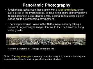
Panoramic Imaging. DHY 202 Clinical Radiology I Dental Hygiene Department William Rainey Harper College. Introduction. Peculiarities of the panoramic system result in a unique projection of many anatomical structures in the image.

Panoramic Imaging
E N D
Presentation Transcript
Panoramic Imaging DHY 202 Clinical Radiology I Dental Hygiene Department William Rainey Harper College
Introduction • Peculiarities of the panoramic system result in a unique projection of many anatomical structures in the image. • Produces several unusual anatomical relationships that are not found in any other kind of radiographic projection. (Langland)
Introduction • Most of the peculiarities of normal structural relationships can be explained by one or more of the following eight concepts. (Langland)
Imaging Concepts • Structures adjacent to tooth-bearing areas are visualized • Structures are flattened and spread out • Midline structures may project as single or double Images • Ghost images are formed • Soft tissue shadows are seen • Air spaces are seen • Radiolucencies and radiopacities are seen • Panoramic images are unique (Langland)
Concept 1:Structures Adjacent to Tooth-Bearing Areas are Visualized • Rims of orbits • Infraorbital canal and foramen • Pterygomaxillary fissure • Borders of maxillary sinus • Zygomatic arch • Nasal fossae
Concept 1:Structures Adjacent to Tooth-Bearing Areas are Visualized • Ramus, body & lower border of mandible • TMJ structures: glenoid fossa, articular eminence, condyle • Styloid process • Hyoid bone & Hard palate
Concept 1:Structures Adjacent to Tooth-Bearing Areas are Visualized
Concept 2:Structures are Flattened and Spread Out • The jaws and structures of the of the maxillofacial complex as well as the spine are portrayed as if they were split vertically in half down the midsagittal plane with each half folded outward. (Langland)
Concept 2:Structures are Flattened and Spread Out • Radiographic image is “laid out” on the film, the same way paint is applied to a wall with a roller. (Langland)
Concept 2:Structures are Flattened and Spread Out • Resultant Image: • Nose remains in the middle • Right and left sides of the jaws are on each side of the film • The spine (having been split in half) appears beyond the rami at the extreme right and left edges of the film. (Langland)
Concept 2:Structures are Flattened and Spread Out (Langland)
Concept 2:Structures are Flattened and Spread Out • Acceptable for • structures visualized within the same plane as the film, • and without superimposition of right and left sides of hard tissue (zygomatic arch, mandible) (Langland)
Concept 2:Structures are Flattened and Spread Out • Undesirable in some areas because spread out structures obscure other structures • Examples: • Nasal conchae/fossae projected across maxillary sinus (client back) • Hyoid spread across mandible (chin tipped too low) (Langland)
Concept 2:Structures are Flattened and Spread Out Correct projection of nasal turbinates Nasal turbinates spread out across sinus due to patient positioning error (Langland)
Concept 3:Midline Structures May Project as Single or Double Images • Real image formation: • Single • Double (Langland)
Concept 3:Midline Structures May Project as Single or Double Images • A single, real image is formed when anatomical structure located between rotation center and film (object in front of rotation center) such as anterior teeth, nasal septum, incisive foramen. (Langland)
Concept 3:Midline Structures May Project as Single or Double Images (Langland)
Concept 3:Midline Structures May Project as Single or Double Images • Some midline structures fall within the focal trough twice; beam intercepts these objects twice due to machine rotation (cervical spine, hard palate, hyoid bone, palatal torus, epiglottis). (Langland)
Concept 3:Midline Structures May Project as Single or Double Images • A double real image is a pair of real images formed by objects located in the central portion of the oral & maxillofacial region. • Double images are mirror images of each other. (Langland)
Concept 3:Midline Structures May Project as Single or Double Images (Langland)
Concept 3:Midline Structures May Project as Single or Double Images Double real images formed in central diamond-shaped region Vertical hatch marks = real image formation (Langland)
Concept 3:Midline Structures May Project as Single or Double Images A = Formation of first image B = Formation of second image (Langland)
Concept 3:Midline Structures May Project as Single or Double Images • Structures that normally produce double real images: hard/soft palate, palatal torus, body of hyoid bone, epiglottis, cervical spine • Malpositioning of client produces undesirable double images:nose turbinates, body of hyoid, spine (Langland)
Concept 3:Midline Structures May Project as Single or Double Images Hard Palate Hyoid bone (Langland)
Concept 3:Midline Structures May Project as Single or Double Images Five Characteristics of Double Images • One image is the mirror image of the other • Both images are real • Each image will have the same proportions • Each image will have the same location on the opposite side • Double images only occur with midline structures falling in diamond-shaped zone in the midline (Langland)
Concept 4:Ghost Images are Formed • Formed when object located between xray source and center of rotation (Anatomically the object is behind the rotation center) (Langland)
Concept 4:Ghost Images are Formed Horizontal hatch marks represent the region where ghost images form (Langland)
Concept 4:Ghost Images are Formed (Langland)
Concept 4:Ghost Images are Formed • Midline structures seen at the posterior limits of the image tend to be ghosted onto the central portion of the radiograph (cervical spine, neckchains, lead apron) (Langland)
Concept 4:Ghost Images are Formed • Lateral structures seen at the posterior limits of the image ghosted onto contralateral side of the image (inferior border of mandible, ramus, hard palate, nasal conchae, earrings) (Langland)
Concept 4:Ghost Images are Formed • Six characteristics of Ghost images... • has the same general shape as its real counterpart • appears on the opposite side of the radiograph from its real counterpart • appears higher on the radiograph than its real counterpart (Langland)
Concept 4:Ghost Images are Formed • The ghost image... • is more blurred than its real counterpart • the vertical component of the ghost is more blurred than the horizontal • vertical component of the ghost is always larger than its real counterpart • Ghosts usually result of technique errors (earrings, necklaces, spine etc.) (Langland)
Summary of Single & Double Real Images & Ghost Images Hatch marks: Vertical = Real images Horizontal = Ghost images Both = Single real & ghost Diamond = Double real & ghost (Langland)
Summary of Single & Double Real Images & Ghost Images 1=Real single images of centrals, 2=Real single image of nasal septum, 3=Real single image of soft tissue outline of nose, 5=Double real image of hyoid, 6=Double real image of spine, 7=Double real images of palate, 8=Ghost image of palate
Concept 5:Soft Tissue Shadows are Seen • Soft tissues are outlined: nasolabial fold, soft palate, ear lobes, tongue lips, nose, epiglottis, uvula, dorsum of tongue, posterior pharyngeal wall, palatine tonsil, soft tissues of nasal turbinates and septum, gingiva, retromolar pad & operculums. (Langland)
Concept 5:Soft Tissue Shadows are Seen • Visualization of the tongue, ears, nose and nasal turbinates spread-out are indications of technique errors. (Langland)
Concept 5:Soft Tissue Shadows are Seen 1=Earlobes, 2=Soft palate, 3=Posterior pharyngeal wall, 4= dorsum of tongue, 5=turbinates, 6=mucus retention cyst in sinus (Langland)
Concept 6:Air Spaces are Seen • Appear black • Include: external auditory meatus, nasopharynx, oropharynx, laryngopharynx, palatoglossal, maxillary sinus, nasal fossa • Air space appearing above dorsum of tongue or anterior teeth is a technique error (Langland)
Concept 6: Air Spaces are Seen 1=Nares, 2=Glossopalatine air space, 3= Soft palate, 4=Nasopharyngeal air space 5=Oropharyngeal air space (Langland)
Concept 6: Air Spaces are Seen 1=Nares, 2=Glossopalatine air space, 3=Soft palate, 4=Nasophyaryngeal air space, 5=Oropharyngeal air space, 6=Maxillary sinus, 7=Inferior meatus, 8=Common meatus, 9=Middle meatus (Langland)
Concept 7:Relative Radiolucencies & Radiopacities are Seen • Need to separate shadows originating from parts of machine from those coming from the client. • Machine parts are plastic with density similar to soft tissue • Easy to identify due to geometric/linear configuration (Langland)
Concept 7:Relative Radiolucencies & Radiopacities are Seen • All machine & client components (hard tissue, soft tissue & air) may produce single and/or double real images and ghost images. • Thus, multiple areas consisting of relative density changes are produced. (Langland)
Concept 7:Relative Radiolucencies & Radiopacities are Seen • Effects of Density Changes on Panoramic Radiographs • Air obscures hard tissues • Soft tissue obscures air • Hard tissue obscures soft tissue • Ghost images obscure everything (Langland)
Concept 7:Relative Radiolucencies & Radiopacities are Seen 1=Air obscures hard tissue(ramus), 2=Soft tissue (soft palate) obscures air space (pharyngeal air space), 3=hard tissue (tooth) obscures soft tissue(soft palate), 4=ghost images (markers, spinal column, hard palate) obscure everything (hyoid, mandible & sinus), 6=machine components (Langland)
Concept 7:Relative Radiolucencies & Radiopacities are Seen 1=Air obscures hard tissue/ramus; 2=Soft tissue/soft palate obscures air/pharyngeal air space, 3=hard tissue/tooth obscures soft tissue/soft palate, 4=ghost images/markers-spinal column-hard palate obscure everything, 5=machine components (Langland)
Concept 7:Relative Radiolucencies & Radiopacities are Seen • If pathology is present it will consist of hard tissue, soft tissue or fluid and it will affect one or more of the three tissue components in various ways. (Langland)
Concept 7:Relative Radiolucencies & Radiopacities are Seen • Effects of Disease On Density of Panoramic Radiographs: Disease producing hard tissue cause all three client components (hard tissue, soft tissue & fluid) to become relatively more radiopaque in the region of the disorder. (Langland)
Concept 7:Relative Radiolucencies & Radiopacities are Seen • Effects of Disease On Density of Panoramic Radiographs: A soft tissue pathologic condition within the mineralized component causes it to become more radiolucent, whereas the soft tissue and air components become more radiopaque when a soft tissue disorder is present. Ex: soft tissue lesion in an air space such as the sinus results in a visible opacity superimposed on the air space. (Langland)
Concept 8: Panoramic Radiographs are Unique • Scope of assessment & interpretive potential exceeds that of CIS: • Relationship of teeth can be studied (crown & bridge, ortho, third molars) • Jaws can be studied: ramus, styloid process, tmj, sinus • Excellent for clients with trimus or trauma (Langland)
Concept 8: Panoramic Radiographs are Unique • Excellent projection of a variety of structures on single film which no other imaging system can achieve.