
To Menu
To Menu. High-Pressure System. Low-Pressure System. Breathing System. Ventilator System. Final Status Check. Initial Steps. Anesthesia Gas Machine Checkout Procedure. AGM Check: Initial Steps. 1.1 Calibrate the O2 monitor 1.2 Electrical Power 1.3 Quick Visual

To Menu
E N D
Presentation Transcript
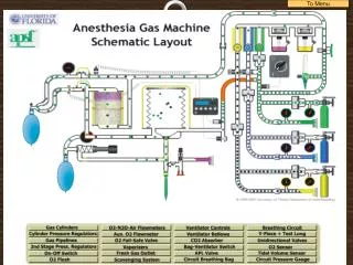
High-PressureSystem Low-PressureSystem BreathingSystem VentilatorSystem Final StatusCheck InitialSteps Anesthesia Gas MachineCheckout Procedure
AGM Check: Initial Steps • 1.1 Calibrate the O2 monitor • 1.2 Electrical Power • 1.3 Quick Visual • 1.4 Back-UP ventilation and Emergency Airway Equipment
1.1 Calibrate O2 monitor Turn on system master switch Ensure monitor reads 21% with sensor in room air Verify low O2 alarm enabled bybreathing on to sensor through your surgical mask Reinstall sensor in circuit - flush breathing system with O2- monitor should read > 95% cannot calibrate - faulty fuel cell crossover between O2 supply and other gas - hospital piping, hoses or in gas machine wrong gas in central supply / cylinder AGM Check: Initial Steps
1.2 Verify Electrical Power Unplug machine power from electrical receptacle (system master switch is still on) Verify “Battery Power OK” message, plug in power cord and message disappears Turn ON vital signs monitor Battery discharged because machine previously left ON and unplugged from AC outlet Allows gas analyzer to “warm up” AGM Check: Initial Steps
1.3 Quick visual check for: Obvious damage / Missing components BioMed notice of Return-to-Service Monitors are present Circuit appears complete Gas sampling line is attached AGM Check: Initial Steps
1.4 Back-up ventilation and emergency airway equipment Self-inflating resuscitation bag Check that the laryngoscopes work Bougie and stylet present Airway device available –LMA, ETT Check for incorrect assembly / damaged parts AGM Check: Initial Steps Back to Menu
AGM Check: High Pressure System • 2.1 Check central pipeline supplies • 2.2 Check O2 reserve cylinder supply
2.1 Check central pipeline supplies Turn off the system master switch Pipeline gauges read 50 – 55 PSI Hoses are connected correctly (colours, DISS) Disconnect O2 pipeline –gauge drops to zero Must be off to check for leak – no minimum flow Misconnections Failure of central O2 supply Line pressure fluctuations AGM Check: High Pressure System
2.2 Check O2 reserve cylinder supply Bleed O2 cylinder pressure to zero with O2 flush(O2 pipeline disconnected) Open O2 cylinder and verify at least half full (approx. 1000 psig) Avoid reading “old” cylinder pressure Check for wrong cylinder - double gasket defeats pin index system or pins are broken Dust protection cap still in place AGM Check: High Pressure System
2.2 Check O2 reserve cylinder supply (cont’d) Listen - no audible leak Close cylinder – pressure gauge drops less than 100 PSI in one min Open and close O2 flowmeter - no flow seen Missing gasket; cylinder not seated in yoke properly Cylinder valve stem loose Unused yoke vacant with no yoke plug Cylinder control valve leaks Machine master switch allows leak AGM Check: High Pressure System (cont’d) Back to Menu
AGM Check: Low-Pressure System • 3.1 Check vaporizer installation • 3.2 Low pressure leak test
3.1 Check vaporizer installation Tops of vaporizers are parallel to manifold - cannot be lifted off manifold Vaporizers are full and fill ports closed Verify all vaporizers OFF Vaporizer not locked on to manifold properly Overfilling of vaporizer AGM Check: Low Pressure System
3.2 Perform low-pressure leak test Do leak test with "suction bulb" device on auxiliary (fresh) gas outlet Verify bulb stays collapsed for > 10 secs Repeat leak test for eachflowmeter (just leave them all on) There should be no flow in the flowmeters Defective suction bulb Leak somewhere between flow control valves and common gas outlet Extends leak test to secondary regulators Cracked, loose, misaligned flow tubes Loose connections – internal piping Faulty system master switch AGM Check: Low Pressure System
3.2 Perform low-pressure leak test Repeat leak test for each vaporizer, one at a time – verify that the vaporizer goes through it’s dial settings then set dial to 1% conc. Verify with each vaporizer that the other vaporizer(s) cannot be turned ON Verify all vaporizers OFF, aux. gas outlet closed Partially open filler/drain port Missing vaporizer port O-ring on manifold Faulty interlock mechanism - can turn on two vaporizers simultaneously Vaporizer will not turn ON - interlock obstructed or vaporizer not seated properly AGM Check: Low Pressure System (cont’d)
3.3 Test flowmeters Put a test lung on the end of the circuit (to collect waste anesthetic gas) Turn on the system master switch Minimum flows are 25ml/min for O2 and zero ml/min for all other gases Flowtubes are undamaged; floats move smoothly throughout their full range Floats sticking - dirt, grease, static Float stuck at top of flow tube Stop broken off from top of flow tube and resting on float No flow – broken tip of needle valve AGM Check: Low Pressure System
3.3 Test flowmeters (cont’d) O2 and N2O flow controls cannot supply hypoxic flowrates – Increase the N2O flow and watch the O2 flow increase - 1.5:.5, 3:1, 6:2 then decrease O2 flow and watch the N2O fall Turn on Air flowmeter and ensure it works through the range and then leave it on Turning vaporizers ON does not lower gas flow(Then verify vaporizer OFF) N2O/O2 3:1 proportioner - linkage broken or gear stop misaligned Obstruction in vaporizer or manifold AGM Check: Low Pressure System (cont’d)
3.4 Verify Oxygen Supply Failure Alarm Set all flowmeters to mid range Drain O2 by pushing flush Distinctive auditory pattern Visual message on vent Ensure that the low O2 pressure stops N2O but not air Turn ON O2 cylinder to silence alarm N20 and Air flow resume Close all 3 gas flowmeters Reconnect O2 pipeline Verify Pipeline pressure Alarm mechanism malfunction No O2 supply alarm when O2 pressure @ 30 PSI Shutoff valve for N2O fails to stop N2O when O2 pressure @ 20 PSI AGM Check: Low Pressure System (cont’d)
3.5 Scavenging System Ensure test lung is in place to collect waste anesthetic gas Selector switch is in Bag/APL position Open APL valve fully – flush occluded circuit with O2 – circuit pressure stays below 10 cm H2O Empty reservoir bag and test lung in order to get rid of waste anesthetic gases into scavenger The scavenger reservoir bag fills and the pressure relief valve releases The scavenger reservoir bag should then deflate Circuit breathing bag does not deflate Hose from circuit to scavenger is blocked Faulty positive pressure relief valve No Vacuum, needle valve closed Too much vacuum and faulty negative pressure relief valve AGM Check: Low Pressure System (cont’d)
AGM Check: Breathing System • 4.1 Check initial status of breathing system • 4.2 Perform leak test - Bag / APL valve circuit • 4.3 Check APL valve • 4.4 Check the function of the unidirectional valves
4.1 Check initial status of breathing system Circuit complete, undamaged, unobstructed Verify CO2 absorbent is adequate (colour, quantity) Attach gas sampling line to circuit Set all flows to zero (or minimum) manufacturing defects causing leaks or obstruction foreign object obstructing e.g. sampling port cap inside elbow AGM Check: Breathing System 2
4.2 Perform leak test - Bag / APL valve circuit Close APL valve (spare breathing bag is still attached to Y-piece) Inflate bag with O2 flush to just < 40 cm H2O Circuit pressure holds steady for > 10 secs Sustained pressure alarm sounds Ventilator bellows does not move Numerous leak sites possible Auxiliary FGF outlet left open (alarm sounds) CO2 canisters not locked into position Faulty canister seals or granules are preventing a good seal CO2 drain plug partially open Unidirectional valve housing loose O2 sensor not firmly seated in port or sensor housing is cracked Flow sensor housing cracked Pressure sensing tubing from gauge is not tightly connected (internal) Leak in breathing bag, circuit hoses Unused sampling ports not capped Faulty selector switch - allows cross-over of gas into ventilator circuit AGM Check: Breathing System
4.3 Check APL valve With APL valve still closed and circuit occluded, squeeze inflated bag until pressure reaches approx. 70 cm H2O High pressure alarm sounds when limit exceeded (e.g. 40 cm H2O) APL valve partially releases Open APL valve slowly until pressure drops below 20 cm H2O, then stop Pressure should stabilize and hold Sustained pressure alarm stops Improperly adjusted APL valve - set to release either too high or too low No alarm - upper limit set too high Cannot adjust pressure - valve sticking (Sustained pressure limit is the high pressure limit or a max of 30 cm H2O) AGM Check: Breathing System 5
4.4 Check function of unidirectional valves Attach a spare breathing bag to the inspiratory outlet of the absorber and close APL valve completely Fill both test bag and reservoir bag with O2 flush until pressure gauge reads 35 cm H2O – pressure should hold Open APL valve – pressure holds but only reservoir bag deflates If needed, repeat test on expiratory inlet with inspiratory outlet occluded Missing, incompetent valves or incorrectly seated If pressure holds - both valves are competent If reservoir bag deflates before opening APL valve - expiratory valve is leaking AGM Check: Breathing System 3
AGM Check: Ventilation Systems • 5.1 Test automatic ventilation system • 5.2 Test manual ventilation system
5.1 Test automatic ventilation system Selector switch set to Ventilator - all flows set to minimum, breathing bag on Y-piece Fill bellows with O2 flush between ventilator breaths - pressure does not exceed 15cm H2O - release flush Set appropriate ventilator parameters for next patient- Inspiration - bellows delivers correct tidal volume - Expiration - bellows fills completely- Volume monitor is consistent with ventilator - Proper action of unidirectional valves Defective ventilator relief valve - should release when > 2.5 cm H2O Relief valve does not close to allow bellows to fill completely Bellows housing not fastened tightly Drive gas hose not firmly attached Connection from absorber to bellows is leaking Volume sensor faulty Valves stick or do not seat properly AGM Check: Ventilation System
5.1 Test automatic ventilation system(cont’d) Remove breathing bag from Y-piece while ventilator is still working Low pressure alarm sounds (“Cannot drive bellows”) until breathing bag is replaced Set selector switch back to Bag/APL (turns ventilator OFF)when bellows fully inflated Ventilator bellows does not drift downward Alarm faulty or ventilator senses pressure 4 - 9 cm H2O with breathing bag off - obstruction somewhere? Leak somewhere – see previous slide AGM Check: Ventilation System 1 (cont’d)
5.2 Test manual ventilation system Switch in Bag/APL mode Ventilate manually and assure inflation and deflation of artificial lungs and appropriate feel of system resistance and compliance Remove second breathing bag from Y-piece Faulty APL valve - incorrect pressure adjustment AGM Check: Ventilation System 2 Back to Menu
AGM Check: Final Status Checks • 6.1 Gas machine and breathing system • 6.2 Monitors
6.1 Gas machine and breathing system Vaporizers OFF Selector switch to Bag/APL and adjust APL valve to MIN Set O2 flow to 3 L/min - other gases to zero Attach face mask to Y-piece and through a surgical mask, breathe in and out through the circuit as final test Set O2 flow to minimum AGM Check: Final Status Checks 1
6.2 Monitors Check that capnometer registers the CO2 from your breath - and apnea alarm sounds after appropriate interval; check alarm settings Check oximeter on your own finger for function; check alarm settings Make sure manual BP cuff is available Patient suction adequate(“thumb test”) AGM Check: Final Status Checks 2 Back to Menu