Download
1 / 70
700 likes | 828 Views
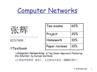
Computer Networks. 张辉 hzhang@buaa.edu.cn 82317650. Textbook Computer Networking: A Top-Down Approach Featuring the Internet by Kurose and Ross 计算机网络教程 谢希仁 人民邮电出版社(2002年5月). What Will We Cover?. 网络简介 网络体系结构 网络物理层(传输媒介、接口、信号) 数据链路层(网络检错、同步、 HDLC 、 PPP )

E N D
Computer Networks 张辉 hzhang@buaa.edu.cn 82317650 • Textbook • Computer Networking: A Top-Down Approach Featuring the Internet by Kurose and Ross • 计算机网络教程 谢希仁 人民邮电出版社(2002年5月) 1: Introduction
What Will We Cover? • 网络简介 • 网络体系结构 • 网络物理层(传输媒介、接口、信号) • 数据链路层(网络检错、同步、HDLC、PPP) • 局域网技术(Ethernet、Token Ring、Token bus) • 网络层(IP 编址、subnetting、VLSM、CIDR) • 路由原理(RIP、OSPF、BGP) • 传输层(TCP 、UDP) • 流量控制、拥塞控制及网络性能 • 应用层(SMTP、ftp、Web、DNS等) • 网络安全及网络管理 • 网络新技术(MPLS、IPv6、Multicasting等) 1: Introduction
Chapter goal: get context, overview, “feel” of networking more depth, detail later in course approach: descriptive use Internet as example Overview: what’s the Internet what’s a protocol? network edge network core access net, physical media performance: loss, delay protocol layers, service models backbones, NAPs, ISPs history ATM network Part I: Introduction 1: Introduction
millions of connected computing devices: hosts, end-systems pc’s workstations, servers PDA’s phones running network apps communication links fiber, copper, radio, satellite routers: forward packets of data thru network router workstation server mobile local ISP regional ISP company network What’s the Internet: “nuts and bolts” view 1: Introduction
protocols: control sending, receiving of msgs e.g., TCP, IP, HTTP, FTP, PPP Internet: “network of networks” loosely hierarchical public Internet versus private intranet Internet standards RFC: Request for comments IETF: Internet Engineering Task Force What’s the Internet: “nuts and bolts” view router workstation server mobile local ISP regional ISP company network 1: Introduction
communication infrastructure enables distributed applications: WWW, email, games, e-commerce, database., voting, more? communication services provided: connectionless connection-oriented cyberspace [Gibson]: “a consensual hallucination experienced daily by billions of operators, in every nation, ...." What’s the Internet: a service view 1: Introduction
human protocols: “what’s the time?” “I have a question” introductions … specific msgs sent … specific actions taken when msgs received, or other events network protocols: machines rather than humans all communication activity in Internet governed by protocols What’s a protocol? protocols define format, order of msgs sent and received among network entities, and actions taken on msg transmission, receipt 1: Introduction
a human protocol and a computer network protocol: TCP connection reply. Get http://gaia.cs.umass.edu/index.htm Got the time? 2:00 <file> time What’s a protocol? Hi TCP connection req. Hi Q: Other human protocol? 1: Introduction
Who is Who on the Internet ? • Internet Engineering Task Force (IETF):The IETF is the protocol engineering and development arm of the Internet. Subdivided into many working groups, which specify Request For Comments or RFCs. • IRTF (Internet Research Task Force):The Internet Research Task Force is a composed of a number of focused, long-term and small Research Groups. • Internet Architecture Board (IAB): The IAB is responsible for defining the overall architecture of the Internet, providing guidance and broad direction to the IETF. • The Internet Engineering Steering Group (IESG): The IESG is responsible for technical management of IETF activities and the Internet standards process. Standards. Composed of the Area Directors of the IETF working groups. 1: Introduction
Internet Standardization Process • All standards of the Internet are published as RFC (Request for Comments). But not all RFCs are Internet Standards ! • available: http://www.ietf.org • A typical (but not only) way of standardization is: • Internet Drafts • RFC • Proposed Standard • Draft Standard (requires 2 working implementation) • Internet Standard (declared by IAB) • David Clark, MIT, 1992: "We reject: kings, presidents, and voting. We believe in: rough consensus and running code.” 1: Introduction
network edge: applications and hosts network core: routers network of networks access networks, physical media: communication links A closer look at network structure: 1: Introduction
end systems (hosts): run application programs e.g., WWW, email at “edge of network” client/server model client host requests, receives service from server e.g., WWW client (browser)/ server; email client/server peer-peer model: host interaction symmetric e.g.: teleconferencing The network edge: 1: Introduction
Goal: data transfer between end sys. handshaking: setup (prepare for) data transfer ahead of time Hello, hello back human protocol set up “state” in two communicating hosts TCP - Transmission Control Protocol Internet’s connection-oriented service TCP service[RFC 793] reliable, in-order byte-stream data transfer loss: acknowledgements and retransmissions flow control: sender won’t overwhelm receiver congestion control: senders “slow down sending rate” when network congested Network edge: connection-oriented service 1: Introduction
Goal: data transfer between end systems same as before! UDP - User Datagram Protocol [RFC 768]: Internet’s connectionless service unreliable data transfer no flow control no congestion control App’s using TCP: HTTP (WWW), FTP (file transfer), Telnet (remote login), SMTP (email) App’s using UDP: streaming media, teleconferencing, Internet telephony Network edge: connectionless service 1: Introduction
mesh of interconnected routers the fundamental question: how is data transferred through net? circuit switching: dedicated circuit per call: telephone net packet-switching: data sent thru net in discrete “chunks” The Network Core 1: Introduction
End-end resources reserved for “call” link bandwidth, switch capacity dedicated resources: no sharing circuit-like (guaranteed) performance call setup required Network Core: Circuit Switching 1: Introduction
network resources (e.g., bandwidth) divided into “pieces” pieces allocated to calls resource piece idle if not used by owning call (no sharing) dividing link bandwidth into “pieces” frequency division time division Network Core: Circuit Switching 1: Introduction
Circuit Switching • Three phases • circuit establishment • data transfer • circuit termination • If circuit not available: “Busy signal” • Examples • Telephone networks • ISDN (Integrated Services Digital Networks) 1: Introduction
Circuit Switching • A node (switch) in a circuit switching network Node incoming links outgoing links 1: Introduction
each end-end data stream divided into packets user A, B packets share network resources each packet uses full link bandwidth resources used as needed, Bandwidth division into “pieces” Dedicated allocation Resource reservation Network Core: Packet Switching resource contention: • aggregate resource demand can exceed amount available • congestion: packets queue, wait for link use • store and forward: packets move one hop at a time • transmit over link • wait turn at next link 1: Introduction
Packet-switching versus circuit switching: human restaurant analogy other human analogies? D E Network Core: Packet Switching 10 Mbs Ethernet C A statistical multiplexing 1.5 Mbs B queue of packets waiting for output link 45 Mbs 1: Introduction
Packet Switching • Data are sent as formatted bit-sequences, so-called packets. • Packets have the following structure: • Header and Trailer carry control information (e.g., destination address, check sum) • Each packet is passed through the network from node to node along some path (Routing) • At each node the entire packet is received, stored briefly, and then forwarded to the next node (Store-and-Forward Networks) • Typically no capacity is allocated for packets Header Data Trailer 1: Introduction
Packet Switching • A node in a packet switching network Node incoming links outgoing links Memory 1: Introduction
1 Mbit link each user: 100Kbps when “active” active 10% of time circuit-switching: 10 users packet switching: with 35 users, probability > 10 active less that .004 Packet switching allows more users to use network! Packet switching versus circuit switching N users 1 Mbps link 1: Introduction
Great for bursty data resource sharing no call setup Excessive congestion: packet delay and loss protocols needed for reliable data transfer, congestion control Q: How to provide circuit-like behavior? bandwidth guarantees needed for audio/video apps still an unsolved problem Is packet switching a “winner?” Packet switching versus circuit switching 1: Introduction
Goal: move packets among routers from source to destination we’ll study several path selection algorithms (chapter 4) datagram network: destination address determines next hop routes may change during session analogy: driving, asking directions virtual circuit network: each packet carries tag (virtual circuit ID), tag determines next hop fixed path determined at call setup time, remains fixed thru call routers maintain per-call state Packet-switched networks: routing 1: Introduction
A B Packet Switching R2 Source Destination R1 R3 R4 • It’s the method used by the Internet. • Each packet is individually routed packet-by-packet, using the router’s local routing table. • The routers maintain no per-flow state. • Different packets may take different paths. • Several packets may arrive for the same output link at the same time, therefore a packet switch has buffers. 1: Introduction
Why does the Internet usepacket switching? • Efficient use of expensive links: • The links are assumed to be expensive and scarce. • Packet switching allows many, bursty flows to share the same link efficiently. • “Circuit switching is rarely used for data networks, ... because of very inefficient use of the links” - Gallager • Resilience to failure of links & routers: • ”For high reliability, ... [the Internet] was to be a datagram subnet, so if some lines and [routers] were destroyed, messages could be ... rerouted” - Tanenbaum 1: Introduction Source: Networking 101
B A Packet Switching R2 Source Destination R1 R3 R4 Host A TRANSP1 “Store-and-Forward” at each Router TRANSP2 R1 PROP1 TRANSP3 R2 PROP2 TRANSP4 R3 PROP3 Host B PROP4 1: Introduction
Packet SwitchingWhy not send the entire message in one packet? M/R M/R Host A Host A R1 R1 R2 R2 R3 R3 Host B Host B Breaking message into packets allows parallel transmission across all links, reducing end to end latency. It also prevents a link from being “hogged” for a long time by one message. 1: Introduction
Q: How to connection end systems to edge router? residential access nets institutional access networks (school, company) mobile access networks Keep in mind: bandwidth (bits per second) of access network? shared or dedicated? Access networks and physical media 1: Introduction
Dialup via modem up to 56Kbps direct access to router (conceptually) ISDN: intergrated services digital network: 128Kbps all-digital connect to router ADSL: asymmetric digital subscriber line up to 1 Mbps home-to-router up to 8 Mbps router-to-home Residential access: point to point access 1: Introduction
HFC: hybrid fiber coax asymmetric: up to 10Mbps upstream, 1 Mbps downstream network of cable and fiber attaches homes to ISP router shared access to router among home deployment: available via cable companies, e.g., MediaOne Residential access: cable modems 1: Introduction
company/univ local area network (LAN) connects end system to edge router Ethernet: shared or dedicated cable connects end system and router 10 Mbs, 100Mbps, Gigabit Ethernet deployment: institutions, home LANs soon Institutional access: local area networks 1: Introduction
shared wireless access network connects end system to router wireless LANs: radio spectrum replaces wire e.g., Lucent Wavelan 10 Mbps wider-area wireless access CDPD: wireless access to ISP router via cellular network router base station mobile hosts Wireless access networks 1: Introduction
physical link: transmitted data bit propagates across link guided media: signals propagate in solid media: copper, fiber unguided media: signals propagate freelye.g., radio Twisted Pair (TP) two insulated copper wires Category 3: traditional phone wires, 10 Mbps ethernet Category 5 TP: 100Mbps ethernet Physical Media 1: Introduction
Coaxial cable: wire (signal carrier) within a wire (shield) baseband: single channel on cable broadband: multiple channel on cable bidirectional common use in 10Mbs Ethernet Physical Media: coax, fiber Fiber optic cable: • glass fiber carrying light pulses • high-speed operation: • 100Mbps Ethernet • high-speed point-to-point transmission (e.g., 5 Gps) • low error rate 1: Introduction
signal carried in electromagnetic spectrum no physical “wire” bidirectional propagation environment effects: reflection obstruction by objects interference Physical media: radio Radio link types: • microwave • e.g. up to 45 Mbps channels • LAN (e.g., waveLAN) • 2Mbps, 11Mbps • wide-area (e.g., cellular) • e.g. CDPD, 10’s Kbps • satellite • up to 50Mbps channel (or multiple smaller channels) • 270 Msec end-end delay • geosynchronous versus LEOS 1: Introduction
packets experience delay on end-to-end path four sources of delay at each hop nodal processing: check bit errors determine output link queueing time waiting at output link for transmission depends on congestion level of router transmission A propagation B nodal processing queueing Delay in packet-switched networks 1: Introduction
Transmission delay: R=link bandwidth (bps) L=packet length (bits) time to send bits into link = L/R Propagation delay: d = length of physical link s = propagation speed in medium (~2x10⁸ m/sec) propagation delay = d/s transmission A propagation B nodal processing queueing Delay in packet-switched networks Note: s and R are very different quantitites! 1: Introduction
R=link bandwidth (bps) L=packet length (bits) a=average packet arrival rate Queueing delay (revisited) traffic intensity = La/R • La/R ~ 0: average queueing delay small • La/R -> 1: delays become large • La/R > 1: more “work” arriving than can be serviced, average delay infinite! 1: Introduction
Networks are complex! many “pieces”: hosts routers links of various media applications protocols hardware, software Question: Is there any hope of organizing structure of network? Or at least our discussion of networks? Protocol “Layers” 1: Introduction
ticket (complain) baggage (claim) gates (unload) runway landing airplane routing ticket (purchase) baggage (check) gates (load) runway takeoff airplane routing airplane routing Organization of air travel • a series of steps 1: Introduction
ticket (complain) baggage (claim) gates (unload) runway landing airplane routing ticket (purchase) baggage (check) gates (load) runway takeoff airplane routing airplane routing Organization of air travel: a different view Layers: each layer implements a service • via its own internal-layer actions • relying on services provided by layer below 1: Introduction
Layered air travel: services Counter-to-counter delivery of person+bags baggage-claim-to-baggage-claim delivery people transfer: loading gate to arrival gate runway-to-runway delivery of plane airplane routing from source to destination 1: Introduction
airplane routing airplane routing airplane routing Distributed implementation of layer functionality ticket (complain) baggage (claim) gates (unload) runway landing airplane routing ticket (purchase) baggage (check) gates (load) runway takeoff airplane routing arriving airport Departing airport intermediate air traffic sites 1: Introduction
Why layering? Dealing with complex systems: • explicit structure allows identification, relationship of complex system’s pieces • layered reference model for discussion • modularization eases maintenance, updating of system • change of implementation of layer’s service transparent to rest of system • e.g., change in gate procedure doesn’t affect rest of system • layering considered harmful? 1: Introduction
HTTP packet radio An Example: No Layering • No layering: each new application has to be re-implemented for every network technology! FTP Telnet Application coaxial cable fiber optic Transmission Media 1: Introduction
packet radio An Example: Benefit of Layering • Solution: introduce an intermediate layer that provides a common abstraction for various network technologies HTTP Telnet FTP Application Transport & Network Transmission Media coaxial cable fiber optic 1: Introduction
ISO OSI Reference Model • Seven layers • lower three layers are hop-by-hop • next four layers are end-to-end Application Application Presentation Presentation Session Session Transport Transport Network Network Network Datalink Datalink Datalink Physical Physical Physical Physical medium 1: Introduction