Download
1 / 24
240 likes | 370 Views
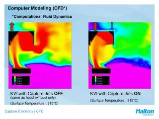
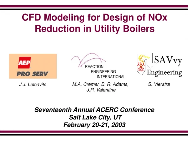
CFD Modeling for Design of NOx Reduction in Utility Boilers. S. Vierstra. M.A. Cremer, B. R. Adams, J.R. Valentine. J.J. Letcavits. Seventeenth Annual ACERC Conference Salt Lake City, UT February 20-21, 2003. Why Use CFD Modeling?. Stringent NO X emissions limits imposed on utilities

E N D
CFD Modeling for Design of NOx Reduction in Utility Boilers S. Vierstra M.A. Cremer, B. R. Adams, J.R. Valentine J.J. Letcavits Seventeenth Annual ACERC Conference Salt Lake City, UT February 20-21, 2003
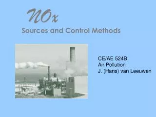
Why Use CFD Modeling? • Stringent NOX emissions limits imposed on utilities • SCR can be used to achieve limits, but is expensive • Other less expensive NOX reduction options such as OFA are available • CFD is a cost effective approach to evaluate options
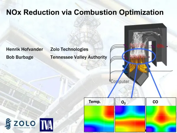
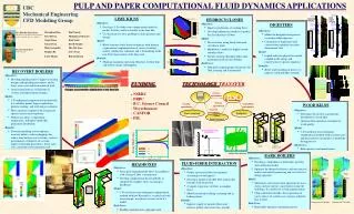
NOx REDUCTION STRATEGIES Staging, OFA, ROFA Reburning, FLGR, SNCR, RRI Co-firing, Fuel Blending & Switching Advanced Concept LNBs & Proof-of-Concept Furnaces OPERATIONAL IMPACTS CO Oxidation Unburned Carbon-in-Ash (LOI) Waterwall Wastage Heat Rate Summary of Reaction Engineering International (REI) Boiler Modeling • over 100 Utility Boilers Modeled • ~37,000 MW Capacity • Cyclone, Turbo, Wall, & T-fired • Firing Coal, Oil, Gas, Biomass, Petcoke, Tires, Blends
Project Objectives • Design and evaluate NOx reduction due to OFA in two units • 265 MW wall-fired PC unit • 530 MW cyclone-fired unit
Wall Fired PC Unit • 265 MW B&W Opposed Wall Fired • 18 Babcock Borsig Power CCV low NOx Burners • Subcritical • Eastern Kentucky bituminous coal (1% Sulfur) • Baseline NOx emissions 0.6 lb/MMBtu Superheater Pendants Partial Division Wall 12 FW Burners 6 RW Burners
Baseline Model265 MW Wall Fired Unit • One-half furnace modeled – symmetry plane • Cartesian grid • 650,000 computational nodes • Vertical model exit downstream of secondary superheater
> 20,000 ppm 0 ppm Predicted CO Distribution265 MW Wall Fired Unit Front Wall Front Wall Proposed OFA Elevation Front Wall
>20,000 CO (ppm) 0 OFA Design Driven by Location of High CO and High Mass Flow Rear Wall Rear Wall > 4.5 Axial Mass Flux (kg/m2/s) < 0 Side Wall Side Wall Symmetry Plane Symmetry Plane Front Wall Front Wall
Proposed OFA Port Layout265 MW Wall Fired Unit • 7 rear wall ports • 4 front wall ports • Interlaced rather than opposed • Elevation 10 ft above top burners • OFA jet velocity 170 ft/sec • Two configurations at different furnace staging levels • Burner modifications to maintain primary to secondary burner velocity ratio
Cyclone Fired Unit • B&W 530 MW, supercritical • Opposed wall-fired • 2 over 3 on front wall • 3 over 3 on rear wall • 60% PRB/40% Eastern bituminous fuel • Barrel water injection for NO2 plume control • Baseline NOx emissions 1.8 – 1.9 lb/MMBtu
Cyclone Barrel Model Cyclone Barrel Model • 10’ diameter • Radial Burner • 350,000 computational cells • Unstaged (SR=1.15) and staged (SR=0.90) were simulated Baseline particle trajectories
Furnace Model • Barrel exit results were interpolated into 750,000 computational cell furnace furnace model • Simulations were performed for the unstaged baseline condition and staged OFA configurations • Baseline results: • Predicted furnace exit gas temperature consistent with observations • Furnace exit CO predicted to be less than 100 ppm • Predicted NOx emissions of 1.96 lb/MMBtu consistent with CEMs
CO (ppm, wet) Initial OFA Port Layout • Ports placed above barrel centerlines • Baseline results suggested that front/rear port distribution should be reversed – structural limitations did not allow this • Staggered ports allow for deeper penetration/improved mixing • 300 ft/s jet velocities • Predictions show high CO pockets in corners, average exit CO 2093 ppm (vs. 85 ppm baseline) 6 rear wall ports 5 front wall ports
CO (ppm, wet) Modified OFA Port Layout • Prediction of high furnace exit CO led to modified design • Addition of 4 low velocity (100 fps) auxiliary ports in the corners • 16% of total OFA flow to auxiliary ports • Main port jet velocity proportionately reduced • Predicted average exit CO 413 ppm (vs. 2093 ppm initial OFA layout) 4 low velocity auxiliary ports
Baseline OFA Case 1 OFA Case 2 CO (ppm, wet) Overall Predictions
Baseline OFA Case 1 OFA Case 2 NOx (ppm, wet) Overall Predictions
Summary • CFD modeling is an effective tool in design and evaluation of NOx reduction technologies in utility boilers • CFD utilized to develop conceptual design of OFA system in 265 MW wall fired furnace fitted with low NOx burners • Model predictions indicated NOx reductions over 30% could be achieved with limited increase in stack CO and carbon in fly ash • Subsequent installation of the OFA system has confirmed predictions • CFD based OFA design developed for 530 MW cyclone fired furnace • Model predictions indicated 80% NOx reduction with small increase in furnace exit CO • Subsequent installation confirmed predictions of 0.37 lb/MMBtu
Acknowledgements • This work was supported by American Electric Power (AEP)