Download
1 / 12
140 likes | 632 Views
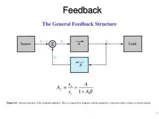
Feedback. The General Feedback Structure. Figure 8.1 General structure of the feedback amplifier. This is a signal-flow diagram, and the quantities x represent either voltage or current signals. Gain Desensitivity. Noise Reduction.

E N D
Feedback The General Feedback Structure Figure 8.1 General structure of the feedback amplifier. This is a signal-flow diagram, and the quantities x represent either voltage or current signals.
Noise Reduction Figure 8.2 Illustrating the application of negative feedback to improve the signal-to-noise ratio in amplifiers.
Reduction in Nonlinear Distortion Figure 8.3 Illustrating the application of negative feedback to reduce the nonlinear distortion in amplifiers. Curve (a) shows the amplifier transfer characteristic without feedback. Curve (b) shows the characteristic with negative feedback (b= 0.01) applied.
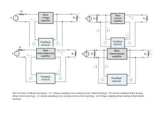
Voltage-Mixing Voltage-Sampling (Series–Shunt) Feedback voltage amplifier
Current-Mixing Current-Sampling (Shunt–Series) Feedback current amplifier let Is increase …
Voltage-Mixing Current-Sampling (Series–Series) Feedback transconductance amplifier
Current-Mixing Voltage-Sampling (Shunt–Shunt) Feedback transresistance amplifier
The Series–Shunt Feedback Amplifier Figure 8.8 The series–shunt feedback amplifier: (a) ideal structure and (b) equivalent circuit.
The Practical Situation Figure 8.10 Derivation of the A circuit and b circuit for the series–shunt feedback amplifier. (a) Block diagram of a practical series–shunt feedback amplifier. (b) The circuit in (a) with the feedback network represented by its h parameters.
Figure 8.11 Summary of the rules for finding the A circuit and b for the voltage-mixing voltage-sampling case of Fig. 8.10(a).
Example 8.1 Figure 8.12 Circuits for Example 8.1.