MicroOperator: Custom Real Time Machine Vision System
MicroOperator: Custom Real Time Machine Vision System. MicroInspector: Post-process Measurement and Inspection Tool. Aligns part during process and compensates for rotation error Halts process if pre-programmed conditions are not met thereby reducing improperly processed parts

MicroOperator: Custom Real Time Machine Vision System
E N D
Presentation Transcript
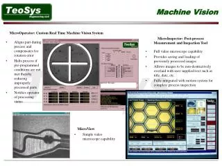
MicroOperator: Custom Real Time Machine Vision System MicroInspector: Post-process Measurement and Inspection Tool • Aligns part during process and compensates for rotation error • Halts process if pre-programmed conditions are not met thereby reducing improperly processed parts • Notifies operator of processing status • Full video microscope capability • Provides saving and loading of previously processed images • Allows images to be non-destructively overlaid with user supplied text such as title, date, etc. • Fully integrated with motion system for complete process inspection MicroView • Simple video microscope capability
MicroMMI: Real Time Machine Vision System • Multiple image processing algorithms (source code) available via proprietary vision system language (Based on RS-274) • Image processing source automatically generated via MicroCaliper program and may be copied into MicroMMI editor • Fully integrated with motion system for pre/post/in-processing inspection, measurement and quality control • Provides full in-process laser and system control • Provides an integrated development environment for operator to single step, edit, and debug motion control programs written in the vision system language • Allows operator to make measurements of features within the live video image once the software has been calibrated to the optics and motion system
The machine vision prototyping application will automatically generate the machine vision PRG programming syntax for each of the commands that the user applies via the user interface. This PRG code can then be copied and pasted into any PRG program that is capable of running with MicroMMI. In order to aid the engineers during experimentation, TeoSys has provided an image and machine vision prototyping application, which can be used to apply the various machine vision algorithms without writing a single line of PRG code. This tuning program allows the user to experiment with all of the machine vision commands before actually using them in a PRG program. Due to the many variables involved when using any kind of image processing, this user interface was designed to provide a nondestructive method of testing which image processing and measurement functions should be used for a particular video stream. All of the functions that are available in this prototyping interface are available via PRG programming commands to the MicrOperator application so that they may be used in real-time in a motion control program.
1. Original Image of Strut 2. Strut Image After High Contrast Auto Threshold The first image has several straight vertical lines in which we need to measure the widths. We attempt to threshold with default high contrast to turn the vertical dark lines into solid vertical dark lines so that we may measure their widths.After applying the automatic threshold function with the default high contrast parameters image number 2 is created. The second and third strut from the left are full of white pixels. It will be impossible to measure the width of those struts unless we can find a way to fill that strut with black along the horizontal of measurement without destroying the accuracy of the measurement.Instead of stopping after the automatic threshold, a series of dilates and erodes were used to fill the interior of the struts with black pixels so that an accurate edge detection measurement could be made. As can be seen from the picture 3, four ROI tools were used purely to outline the struts. It turns out that seven erodes and then seven dilates were used to fill in the struts as in picture 3. The Erode tool expands the dark pixels so that there is no white in the center of some feature. In the above picture, only a very small amount of white pixels remained inside the strut. When the Dilate tool is applied, only the white areas will expand in size. Since most of the white was removed from the strut, there was no white area to expand. 3. Struts After 7 Erodes and 7 Dilates
The geometrical Search tool is a very good tool to use when searching for a pattern that moves around the master image, changes intensity, suffers from blurring or defocusing, and for patterns that reverse their contrast. Image number 1 was used to train a fiducial pattern. The ROI was drawn around the fiducial so that the ROI bounding box just enclosed the fiducial fully. After the training was complete, a new image was loaded that was a picture of the same fiducial but its location within the master image had changed and it was severely defocused. The geometrical search algorithm had no problem finding the fiducial in picture number 2. 1. Original Fiducial Image Used to Train Fiducial Pattern The Search tool can be used to find a trained pattern within the master image (field of view) and make a decision to continue based on the presence or absence of the fiducial or on the fiducial’s location. All patterns must have geometrical characteristics that can be seen such as the fiducial above. The pattern must be unique and different from the rest of the image. It is best to have images that respond well to the Bi-Level threshold. If the master image (or field of view) responds well to the Bi-Level, then most characteristics should be able to be found. 2. Image of Defocused and Moved Fiducial