Download

1 / 23
230 likes | 329 Views
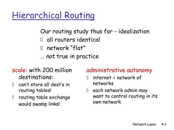
Learn about hierarchical routing in Internet networks to handle complexity as network size grows. Understand intradomain and interdomain routing, autonomous systems, gateway setup, and routing protocols. Case studies on IP fragmentation, RIP, OSPF, and BGP illustrate different routing techniques. Explore how routers communicate and optimize traffic flow using hierarchical structures.

E N D
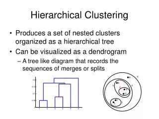
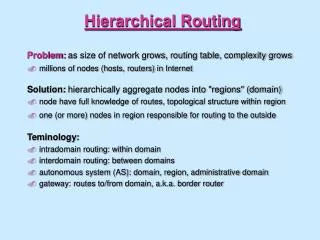
Hierarchical Routing Problem: as size of network grows, routing table, complexity grows • millions of nodes (hosts, routers) in Internet Solution: hierarchically aggregate nodes into "regions" (domain) • node have full knowledge of routes, topological structure within region • one (or more) nodes in region responsible for routing to the outside Teminology: • intradomain routing: within domain • interdomain routing: between domains • autonomous system (AS): domain, region, administrative domain • gateway: routes to/from domain, a.k.a. border router
Hierarchical Routing (cont) Three domains: A, B, C A.a, A.b A.c run interdomain routing protocol A.c, B.a, B.b, C.a run intradomain routing protocol among themselves
Different routing protocols can be used for interdomain and intradomain routing A.a routing table: A look inside A.c: Hierarchical Routing (cont)
Hosts and routers Hosts (end systems) typically perform no routing • start packets on their way • send packets to nearest router Q: how do hosts learn identity of nearby router: • A1: IP address of router hard-coded into file (see /etc/networks on many UNIX systems) • A2: router discovery: RFC 1256 • router periodically broadcasts its existence to attached hosts • host (on startup) broadcasts query (who is my router) on attached links/LANs
Fields in IP packet: version number: (of IP protocol), current version is 4, new version is 6 header length: because of options, length of header is variable TOS: not used, idea was to allow different levels of reliability, real-time, etc packet length: header plus data identifier: used with IP fragmentation to identify fragments belonging to same original IP packet flags: 2 bits: do not fragment, more fragments fragmentation offset: if this a fragment, where it belongs in original packet time-to-live: decremented by each router, so a packet will not loop forever in the net protocol: which upper layer protocol to demultiplex to. See RFC 1700 header checksum: recomputed at each hop, as TTL changes source, dest IP address: of original sender, and eventual recipient Network Layer Case Study: the Internet
IP fragmentation and Reassembly • transport layer packet may be too big to send in single IP packet • underlying data link protocol will constraint maximum IP length • fragmentation: IP packet divided into fragments by IP • each fragment becomes its own IP packet • each address has same identifier, source, destination address • fragment offset gives offset of data from start of original packet • more fragment bit: 0 means last bit in this fragment • fragments not reassembled until final destination
Internet Intradomain Routing: RIP RIP: Routing Information Protocol, uses distance vector algorithm, with link costs of 1 • shortest path • routing table sent to neighbors every 30 seconds, or when route costs change Implemented as a daemon (user-level process) • communicates with other attached router using UDP packets • note: UDP packets can be lost! • if route via neighbor not updated in 3 minutes, timeout route (set cost to infinity) • called routed on UNIX systems
A RIP routing table Example table taken from freya.cs.umass.edu: ~ netstat -rn (note: on freya.cs.umass.edu)
Internet Intradomain Routing: OSPF OSPF: open shortest path first • open: a published standard (RFC 1247) • interior gateway protocol: for intradomain outing within an autonomous system (AS) • uses link state algorithm to determine routes • each outgoing link (interface) assigned dimensionless cost • different cost can be used for different TOS • load balancing: with several equal-cost-paths to destination, will distribute load across both paths Support for hierarchy: • autonomous system divided into "areas" • one area designated "backbone" • area border routers in backbone route between areas • other routers in backbone also • AS boundary router talks to outside world
Intra-area routing: never cross backbone To get from one area to another: source area -> backbone -> destination area area router:red boundary router:blue Internet Intradomain Routing: OSPF (cont)
Interdomain Internet Routing: BGP BGP: Border Gateway Protocol • routing between nodes in different autonomous systems (i.e., routing between networks) • RFC 1267, 1268 • uses a distance verctor approach Policy-Based Routing • rather than costs to destinations, BGP routers exchange full path information (networks crossed) to destination router can decide on policy basis which route to take • e.g. "traffic from my AS should not cross AS's a,b,c,d" • BGP implementation: • implemented as a daemon (user-level process) • communicates with other BGP routers using TCP
ICMP: Internet Message Control Protocol • used to communicate network-level error conditions and info to IP/TCP/UDP protocols or user processes • often considered part of IP, but • ICMP message sent within IP datagram • IP demultiplexes up to ICMP using IP protocol field • ICMP message contains IP header and first 8 bytes of IP contents that causes ICMP mesage to be generated
Changes to Ipv4: 128 bit addresses (so we don't run out of IP addresses) header simplification (faster processing) more support for type of service priorities flow identifier: identifiy packets in a connection security Notes: no fragmentation in network packet too big generates ICMP error to source source fragmentation via extension header no checksum (already done at transport and data link layer) IPv6: next generation IP
Transitioning from IPv4 to IPv6 Internet too big for "flag day": • can't turn off all IP routers, install IPv6 and reboot • IPv4 nodes will be legacy • IPv6 nodes can route IPv4 packets • IPv4 nodes can not route IPv6 packets Tunneling: • source and destination speak network protocol X • physically intermediate nodes speak network protocol Y • source takes protocol X packet, sticks it inside (encapsulates) protocol Y packet • intermediate nodes route using protocol Y • destination receives packet using protocol Y, removes protocol X packet • network between source and destination looks like a single link to protocol X
Case Study: ATM Network Layer • ATM: packet (cell) format: • UNI: user-network interface (host-to-switch) • NNI: network-network interface (switch-to-switch) • GFC: generic flow control (unused) • VPI: virtual path identifier • VCI: virtual circuit identifer • VPI and VCI together a call/connection identifier • PTI: payload type: 3 bits • 111: RM cell (recall RM congestion control) • 000: user cell • 010: user cell, congestion experienced (recall EFCI) • CLP: cell loss priority (1 bit) • priority bit for discarding • HEC: header error correction • DATA: 48 bytes of data
Observations about ATM Cell • very small • reflecting telephony origins • 48 bytes a compromise, halfway 64 and 32 • no explicit source/destination address • VCI/VPI used instead • faster switching (VPI/VCI can index into table) • 28 bit VPI/VCI for switching instead of 128 bit IP address in IPv6 (savings) • fixed length for faster switching • minimal priority
ATM networks: Virtual-circuit Oriented • VCI/VPI together identify call • multiple calls (VCI) bundled into same VP • network can switch on VP basis only • less state (network only sees VP's) • all VC's in VP follow same path
Connection Setup in ATM • messages ("signaling") used to setup up call through network • state info (VP switching info - which output line to switch incoming VC) set up in switches • meaning of call setup messages:
ATM Call Setup (cont) Observations: • unlike Internet, switches involved in call setup • state creation • ACKing between switches • wait one RTT before sending data • unlike UDP • same as TCP • what if connection breaks? • other switches must remove state • ATM standard does not specify a routing protocol
Input interface cards: physical layer processing memory buffers to hold incoming packet Switch fabric: to move packets from input to output Output interface cards: memory buffers to hold outgoing packets physical layer processing Control processor: routing table updates, supervisory (management) functions will typically not touch the packets being switched Switches and Routers: What's Inside
Switching Fabrics Two popular ways to switch: • switching via memory: input line ports write to memory, output ports read from memory • switching via a bus: bus (backplane) connects input and output ports • e.g.: Cisco AGS+ has 533 Mbps backblane bus
Network Layer: Summary Network service: datagram versus VC Theory of routing protocols • link state and distance vector • multicast • broadcasting Case studies: • Internet • IPv4, IPv6 • protocols for exchanging routing information: RIP, OSPF, BGP • ATM