Download
1 / 47
470 likes | 539 Views
Hierarchical Scheduling. Fabric. Rewrite Marker. CoS Processing—Hierarchical Scheduling. Ingress. Forwarding Policy. BA Classifier. Policing (Ingress). Multifield Classifier. Scheduler. Shaper. RED. Scheduler. Shaper. RED. Egress. Scheduler. Shaper. RED. Multifield Classifier.

E N D
Fabric RewriteMarker CoS Processing—Hierarchical Scheduling Ingress Forwarding Policy BA Classifier Policing (Ingress) Multifield Classifier Scheduler Shaper RED Scheduler Shaper RED Egress Scheduler Shaper RED Multifield Classifier Policing (Egress) Scheduler Shaper RED
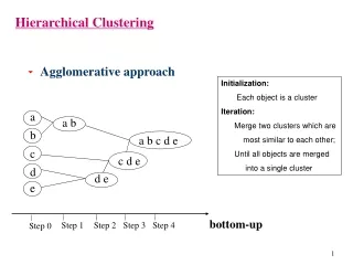
Hierarchical Scheduling Overview • Role of hierarchical CoS: • Allows tiered shaping, scheduling, and queuing • Provides fine-grained control over CoS treatment at multiple levels • Examples: CoS per customer (VLAN), and per port (physical interface) • Each level is functionally similar to port-level CoS • Capabilities vary somewhat per level • Centralizes CoS enforcement and configuration • Provides CoS capabilities for downstream devices that lack CoS functionality • Reduces need to configure CoS on downstream devices • H-CoS requires specific hardware • See the following slide
Hardware Requirements for Hierarchical Scheduling • Specific hardware is required • MX Series • Enhanced queuing DPC or MPC • M Series and T Series • IQ, IQE, IQ2, IQ2E PICs • This material is based on EQ-DPC • EQ-MPC and IQ2E PIC have very similar feature sets, with slight variations • Other PICs have varied subsets of these features Refer to the Junos Class of Service Configuration Guide for detailed information on hardware-based CoS variations.
Hierarchical Scheduling Concepts (1 of 2) • Terminology • Customer VLAN (C-VLAN) • The inner VLAN tag of a stacked VLAN; often corresponds to customer CPE • Scheduling and shaping is often used on a C-VLAN to establish minimum and maximum bandwidth limits for a customer • Service VLAN (S-VLAN) • The outer VLAN tag of a stacked VLAN; often corresponds to a network aggregation device such as a DSLAM • Scheduling and shaping is often established for an S-VLAN to provide CoS for downstream devices with little buffering and simple schedulers
Hierarchical Scheduling Concepts (2 of 2) • Terminology (contd.) • Traffic control profile • Configuration component containing scheduler and queuing properties • Specifically for H-CoS context; applied at physical interface, interface set, and logical interface (VLAN) levels • Interface set • User-defined group of logical interfaces (C-VLANs) or S-VLANs • Committed information rate (CIR) • The guaranteed rate assigned to an interface set or VLAN • Peak information rate (PIR) • The maximum rate assigned to a port, interface set or VLAN • Also called the shaping rate
Queuing and Scheduling • Hierarchical per-VLAN queuing • CoS at up to four levels: • Level 1—Physical interface (port) • Level 2—Interface set (VLAN or logical interface group) • Level 3—Logical interface (VLAN) • Level 4—Queue • Up to 8 queues per logical interface (VLAN) • Each queue has its own scheduling properties • Transmission rate, priority, delay buffers, RED drop profiles
Hierarchical Scheduling Illustrated Reference Model Level 4 Level 1 Level 3 Level 2 KJ Buffer PIR PIR VLAN INTERFACE-SET CIR CIR PIR PIR PQ-DWRR Scheduler PIR CIR Transmit VLAN INTERFACE-SET CIR Port Shaper PIR PIR VLAN INTERFACE-SET CIR CIR Queues KJ WRED Scheduler KJ KJ DROP Shapers Shapers
Scheduler Modes • Scheduler configuration modes—available on a per-port basis • Per-unit scheduler • Port-level shaping • Logical interface (VLAN) scheduling and queuing • Full queue scheduling • Hierarchical scheduler • Port-level shaping • Interface set scheduling and queuing • Logical interface (VLAN) scheduling and queuing • Full queue scheduling No interface sets
Per-Unit Scheduler Mode Level 3 Level 1 Level 4 • Port configured with per-unit scheduler mode • Shaping per port • Scheduler allocated to every VLAN under the port KJ Buffer PIR VLAN CIR Transmit PIR PQ-DWRR Scheduler PIR CIR VLAN Port Shaper PIR VLAN CIR Queues WRED Scheduler KJ KJ DROP No interface sets Shapers
Hierarchical Scheduler Mode Level 4 Level 1 Level 2 Level 3 VLAN 10 PIR PIR VLAN 11 CIR CIR Remaining: VLANs 12,13,14 INTERFACE-SET A Transmit PQ-DWRR Scheduler VLAN 20 PIR PIR Port Remaining: VLANs 21,22,23 CIR INTERFACE-SET B Queues VLAN 30 WRED Scheduler “Remaining” schedulers are discussed on subsequent pages. DROP Remaining: VLANs 31,32
Enabling a Scheduler Mode Hierarchical scheduling Per-unit scheduling [edit] user@R1# show interfaces ge-0/0/0 { hierarchical-scheduler; vlan-tagging; unit 100 { vlan-id 100; family inet { address 192.168.1.1/24; } } unit 200 { vlan-id 200; family inet { address 192.168.2.1/24; } } } [edit] user@R1# show interfaces ge-0/0/0 { per-unit-scheduler; vlan-tagging; unit 100 { vlan-id 100; family inet { address 192.168.1.1/24; } } unit 200 { vlan-id 200; family inet { address 192.168.2.1/24; } } } Configurable on a per-port basis.
Level 1—Port (1 of 2) • Shaping • PIR • Maximum rate for physical interface • Can “shape down” to less than interface speed
Level 1—Port (2 of 2) • CoS configuration • Use a traffic control profile • Set PIR (shaping-rate) • Apply to port Example [edit class-of-service] user@R1# show traffic-control-profiles { L1-port-profile { shaping-rate 100m; } } interfaces { ge-0/0/0 { output-traffic-control-profile L1-port-profile; } } } PIR Port
Level 2—Interface Set (1 of 3) Example • Interface set configuration • Interface set creation • Select individual logical interfaces (VLANs), or.. • Identify a group of dual-tagged VLANs by S-VLAN tag • Usage notes: • Ranges are not supported • Cannot mix interface set types • One physical interface per interface set • A logical interface or S-VLAN tag can only belong to one interface set [edit interfaces] user@R1# show interface-set A { interface ge-0/0/0 { unit 100; unit 200; } } interface-set B { interface ge-0/0/0 { vlan-tags-outer 1234; } } ge-0/0/0 { hierarchical-scheduler; flexible-vlan-tagging; unit 100 { vlan-id 100; } unit 200 { vlan-id 200; } unit 1000 { vlan-tags outer 1234 inner 1000; } unit 1100 { vlan-tags outer 1234 inner 1100; } }
Level 2—Interface Set (2 of 3) • Shaping • CIR and PIR • Guaranteed and maximum rates for interface set • Scheduling • CIR and PIR determine relative weight between interface sets • Bandwidth sharing modes (per-port basis): • CIR mode—If any interface set has CIR defined, sharing is based on CIR • PIR mode—If no interface set has CIR defined, sharing is based on PIR • When traffic exceeds PIR, interface set stops transmitting
Level 2—Interface Set (3 of 3) • CoS configuration • Use a traffic control profile • Set CIR (guaranteed-rate) and PIR (shaping-rate) • Apply to interface set Example [edit class-of-service] user@R1# show traffic-control-profiles { L2-interface-set-profile { shaping-rate 75m; guaranteed-rate 50m; } } interfaces { interface-set A { output-traffic-control-profile L2-interface-set-profile; } } PIR INTERFACE-SET CIR
Level 3—Logical Interface (VLAN) (1 of 2) • Shaping • CIR and PIR • Scheduler map—references associated queues • Scheduling • CIR and PIR determine relative weight between VLANs • Bandwidth sharing modes (per-port basis): • CIR mode—If any VLAN has CIR defined, sharing based on CIR • PIR mode—If no VLAN has CIR defined, sharing based on PIR • When traffic exceeds PIR, VLAN stops transmitting Excess bandwidth (bandwidth not allocated to VLAN CIRs) sharing is also proportionate to CIR by default.
Level 3—Logical Interface (VLAN) (2 of 2) • CoS configuration • Use a traffic control profile • Set CIR (guaranteed-rate) and PIR (shaping-rate) • Apply scheduler map (references level 4 queues) • Apply to logical interface Example [edit class-of-service] user@R1# show traffic-control-profiles { L3-unit-profile { scheduler-map sched-map-example; shaping-rate 30m; guaranteed-rate 20m; } } interfaces { ge-0/0/0 { output-traffic-control-profile L1-port-profile; unit 100 { output-traffic-control-profile L3-unit-profile; } } } PIR CIR VLAN
Level 4—Queue (1 of 2) • Scheduling • Standard scheduler • Transmission rate, priority, delay buffers, RED drop profiles • Same as for port-level queuing • H-CoS slightly affects some functionality • Discussed subsequently Buffer PIR CIR VLAN Queues
Level 4—Queue (2 of 2) Example [edit class-of-service] drop-profiles { aggressive { interpolate { . . . } } relaxed { interpolate { . . . } } } scheduler-maps { sched-map-example { forwarding-class best-effort scheduler sch-be; forwarding-class network-control scheduler sch-pri; } } schedulers { sch-be { transmit-rate percent 70; buffer-size percent 70; priority low; drop-profile-map . . . drop-profile aggressive; drop-profile-map . . . drop-profile relaxed; } sch-pri { transmit-rate percent 30; buffer-size percent 30; priority high; } } • CoS configuration • Configure scheduler, including drop profiles • Transmission rate • Queue priority • Delay buffers • Drop profiles • Drop profile maps • Configure scheduler map • Apply scheduler map • Scheduler map was already applied within the L3 VLAN’s traffic control profile
H-CoS Throughput Example (1 of 4) Shaping Rate 200 Mbps VLAN 10 2 Mbps Guaranteed Rate 200 Mbps INTERFACE-SET A 20 Mbps 200 Mbps VLAN 20 4 Mbps Port 200 Mbps 200 Mbps VLAN 30 200 Mbps 5 Mbps INTERFACE-SET B 40 Mbps 200 Mbps VLAN 40 15 Mbps Each VLAN has 3 queues
H-CoS Throughput Example (2 of 4) Reminder: Excess bandwidth sharing is proportionate to CIR by default. • Expected throughput behavior • Throughput of the port is 200 Mbps • Interface sets A and B share the total port bandwidth in a 1:2 ratio • VLANs 10 and 20 share interface set A’s bandwidth in a 1:2 ratio • VLANs 30 and 40 share interface set B’s bandwidth in a 1:3 ratio • At each VLAN level, the queues share the VLAN’s bandwidth in a 2:3:5 ratio
H-CoS Throughput Example (3 of 4) • Throughput results • For the port, the interface sets: • Use up their guaranteed bandwidth of 60 Mbps • Share the excess bandwidth in the ratio of 20 Mbps : 40 Mbps • For interface set A, the VLANs: • Use up their guaranteed bandwidth of 6 Mbps • Share the excess bandwidth in the ratio of 2 Mbps : 4 Mbps • For interface set B, the VLANs: • Use up their guaranteed bandwidth of 20 Mbps • Share the excess bandwidth in the ratio of 5 Mbps : 15 Mbps
H-CoS Throughput Example (4 of 4) • Throughput calculations • Available port throughput: 200 Mbps • Interface set A: CIR + 1:2 ratio of 140 Mbps (remaining on port) • 20 Mbps + 46.7 Mbps = 66.7 Mbps • VLAN 10: CIR + 1:2 ratio of 60.7 Mbps (remaining on int. set) • 2 Mbps + 20.2 = 22.2 Mbps • Queue 0: 20% of 22.2 Mbps (VLAN 10) • 20% x 22.2 = 4.4 Mbps
Remaining Traffic • Remaining traffic • All logical units (VLANs) without a traffic control profile applied • Grouped per interface set • One group for VLANs not in interface sets • Remaining schedulers • Identical to regular L3 logical interface (VLAN) scheduler • Each remaining traffic group shares one scheduler, one set of queues
Remaining VLANs Level 3 Level 4 Level 2 Level 1 Remaining traffic for interface set VLAN 10 PIR PIR VLAN 11 CIR CIR Remaining: VLANs 12,13,14 INTERFACE-SET A Transmit PQ-DWRR Scheduler VLAN 20 PIR PIR Port Remaining: VLANs 21,22,23 CIR INTERFACE-SET B Queues VLAN 30 Remaining traffic for port WRED Scheduler DROP Remaining: VLANs 31,32
Remaining VLANs—Interface Set • CoS configuration • Use a traffic control profile • Same as L3 logical interface (VLAN) configuration • Set CIR (guaranteed-rate) and PIR (shaping-rate) • Apply scheduler map (references level 4 queues) • Apply to interface set • Use output-traffic-control-profile-remaining statement Example [edit class-of-service] user@R1# show traffic-control-profiles { L3-VLAN-profile-remaining { scheduler-map sched-map-example; shaping-rate 30m; guaranteed-rate 20m; } } interface-set A { output-traffic-control-profile L2-interface-set-profile; output-traffic-control-profile-remaining L3-VLAN-profile-remaining; }
Remaining VLANs—Port • CoS configuration • Use a traffic control profile • Same as L3 logical interface (VLAN) configuration • Set CIR (guaranteed-rate) and PIR (shaping-rate) • Apply scheduler map (references level 4 queues) • Apply to logical interface • Use output-traffic-control-profile-remaining statement Example [edit class-of-service] user@R1# show traffic-control-profiles { L3-VLAN-profile-remaining { . . . } } ge-0/0/0 { output-traffic-control-profile L1-port-profile; output-traffic-control-profile-remaining L3-VLAN-profile-remaining; unit 100 { output-traffic-control-profile L3-unit-profile; } }
Queue Priority • Effect of interface sets and VLANs on queue scheduling • Queues have two priorities, based on VLAN rate • VLAN < CIR = queue priorities function normally • CIR < VLAN < PIR < = all priorities (except strict-high) become excess *On EQ-DPCs, medium-high and medium-low software queues share a hardware queue.
Priority Queuing Process for H-CoS Interface Set VLAN • How priority queuingworks in H-CoS context: • VLANs and interface sets compete for a port’s bandwidth • Transmit from all strict-high and high priority queues • Transmit from medium priority queues • Transmit from low priority queues • Transmit from excess priority queues Strict-High Strict-High Serviced First VLAN < CIR VLAN < CIR High High Med-High Med-High Med-Low Med-Low Round Robin Low Low CIR < VLAN < PIR CIR < VLAN < PIR Weighted Round Robin Excess Excess Serviced Last
Transmission Rate (1 of 2) • Excess bandwidth (bandwidth not allocated to VLAN CIRs) • Shared using one of three modes: • CIR mode—proportional to CIR (default) • PIR mode—proportional to PIR • Equal sharing • Can set mode per port • Applies to all interface sets • Can set mode per interface set • Applies to all contained VLANs; overrides port mode setting
Transmission Rate (2 of 2) • Excess bandwidth sharing—configuration • Sharing proportional to CIR or PIR • Set equal to maximum effective transmission rate among all queues under a port or interface set • Factor of VLAN CIR and queue transmission rate • Sharing equally • Use equaloption Example [edit class-of-service interfaces] user@R1# show interface-set A { excess-bandwidth-share equal; } } ge-0/0/0 { excess-bandwidth-share proportional 14000000; } }
Delay Buffers (1 of 3) • Buffer size • Rate used to determine delay buffer for port-based queuing is interface bandwidth (implicitly known value) • Rate used to determine delay buffer is VLAN bandwidth • VLAN bandwidth is not implicitly known; must be configured in VLAN traffic control profile • Delay buffer rate—configurable parameter, provides reference for buffer size calculation • Buffer size is calculated implicitly using CIR (if no delay buffer rate) or PIR (if no CIR) • Maximum buffer size for EQ-DPC = 500 ms • Varies for other hardware • No dynamic memory allocation • Buffers are not elastic for H-CoS
Delay Buffers (2 of 3) Example [edit class-of-service] traffic-control-profiles { . . . L3-unit-profile { scheduler-map sched-map-example; shaping-rate 30m; guaranteed-rate 20m; delay-buffer-rate 40m; } } interfaces { . . . ge-0/0/0 { output-traffic-control-profile L1-port-profile; unit 100 { output-traffic-control-profile L3-unit-profile; } } } schedulers { sch-be { transmit-rate percent 70; buffer-size percent 70; priority low; drop-profile-map . . . drop-profile aggressive; drop-profile-map . . . drop-profile relaxed; } sch-pri { transmit-rate percent 30; buffer-size percent 30; priority high; } } scheduler-maps { sched-map-example { forwarding-class best-effort scheduler sch-be; forwarding-class network-control scheduler sch-pri; } } • Calculating effective buffer size for queues • L4 queues’ schedulers use L3 delay buffer rate as reference bandwidth • VLAN bandwidth becomes ‘interface bandwidth’ for calculating buffer size • Same calculations as for port-level queuing • If no delay buffer rate, system uses CIR • If no CIR, system uses PIR
Delay Buffers (3 of 3) Example • Allocating buffer space • Levels 1–3 support delay buffer rate configuration • Each level uses level below as reference bandwidth • Sum of buffers at each level must not exceed level below [edit class-of-service] traffic-control-profiles { L1-port-profile { shaping-rate 100m; delay-buffer-rate 200m; } L2-interface-set-profile { shaping-rate 75m; guaranteed-rate 50m; delay-buffer-rate 100m; } L3-unit-profile { scheduler-map sched-map-example; shaping-rate 30m; guaranteed-rate 20m; delay-buffer-rate 35m; } } interfaces { interface-set A { output-traffic-control-profile L2-interface-set-profile; } ge-2/0/0 { output-traffic-control-profile L1-port-profile; unit 100 { output-traffic-control-profile L3-unit-profile; } } }
RED Drop Profiles • Drop profiles • Use segmented, with only two fill levels • Minimum queue depth; below it, drop probability is 0 • Maximum queue depth; above it, drop probability is 100 • Linear increase in drop probability between min. and max. queue depth 100 Example Drop Probability [edit class-of-service] drop-profiles { segmented-style-profile { fill-level 25 drop-probability 0; fill-level 90 drop-probability 90; } } } 0 Max queue depth Min queue depth Average Queue Depth
Configuring Hierarchical Scheduling • Configuration steps: • Configure physical interface for H-CoS • Add hierarchical-scheduler statement • Configure interface sets • Configure schedulers, including drop profiles • Configure scheduler maps • Associate schedulers and forwarding classes • Configure traffic control profiles • Associate scheduler maps to logical interfaces (VLANs) • Apply traffic control profiles to ports, interface sets, and logical interfaces (VLANs)
Configuration Example Illustrated Level 3 Level 1 Level 4 Level 2 Unit 0VLAN 10 PIR 200 Mbps CIR 2 Mbps PIR 200 Mbps Unit 1VLAN 11 INTERFACE-SET A PIR 200 Mbps CIR 20 Mbps CIR 4 Mbps Unit 2,3,4VLAN 12,13,14 Queue 020% transmit-rate PIR 200 Mbps CIR 4 Mbps Queue 130% transmit-rate Port PIR 200 Mbps Unit 5VLAN 30 PIR 200 Mbps Queue 250% transmit-rate CIR 5 Mbps Unit 6VLAN 31 PIR 200 Mbps CIR 15 Mbps Unit 7,8,9VLAN 32,33,34 PIR 200 Mbps CIR 15 Mbps
Configuring Physical Interface for H-CoS Example Enable H-CoS on physical interface [edit interfaces] ge-0/0/0 { hierarchical-scheduler; vlan-tagging; unit 0 { vlan-id 10; . . .; } } unit 1 { vlan-id 11; . . .; } } . . . }
Configuring Interface Sets Example Configure logical units within interface set [edit interfaces] interface-set A { interface ge-0/0/0 { unit 0; unit 1; unit 2; unit 3; unit 4; } }
Configuring Schedulers and Drop Profiles Example [edit class-of-service] schedulers { sched-q0 { transmit-rate percent 20; buffer-size percent 20; } sched-q1 { transmit-rate percent 30; buffer-size percent 30; } sched-q2 { transmit-rate percent 50; buffer-size percent 50; } } Configure properties of queues using schedulers No drop profiles are configured in this example.
Configuring Scheduler Maps Schedulers do nothing until they are referenced in a scheduler map. Example Associate schedulers to queues/forwarding classes [edit class-of-service] scheduler-maps { scheduler-map-q0-q1-q2 { forwarding-class fc0 scheduler sched-q0; forwarding-class fc1 scheduler sched-q1; forwarding-class fc2 scheduler sched-q2; } }
Configuring Traffic Control Profiles Example [edit class-of-service] traffic-control-profiles { profile-set-A { shaping-rate 200m; guaranteed-rate 20m; } profile-PIR-200M-CIR-5M { scheduler-map scheduler-map-q0-q1-q2; shaping-rate 200m; guaranteed-rate 5m; } profile-PIR-200M-CIR-15M { scheduler-map scheduler-map-q0-q1-q2; shaping-rate 200m; guaranteed-rate 15m; } profile-PIR-200M-CIR-2M { scheduler-map scheduler-map-q0-q1-q2; shaping-rate 200m; guaranteed-rate 2m; } profile-PIR-200M-CIR-4M { scheduler-map scheduler-map-q0-q1-q2; shaping-rate 200m; guaranteed-rate 4m; } } Configure traffic control profile for interface set Configure a 200 M, 5 M scheduler with 3 queues Configure a 200 M, 15 M scheduler with 3 queues Configure a 200 M, 2 M scheduler with 3 queues Configure a 200 M, 4 M scheduler with 3 queues
Applying Traffic Control Profiles—Port and Interface Set Example Configure excess bandwidth share for the whole interface [edit class-of-service] interfaces { ge-0/0/0 { excess-bandwidth-share proportional 25500000; output-traffic-control-profile-remaining profile-PIR-200M-CIR-15M; interface-set A { excess-bandwidth-share proportional 25500000; output-traffic-control-profile profile-set-A; output-traffic-control-profile-remaining profile-PIR-200M-CIR-4M; } } } Configure scheduling properties for VLANs 32, 33, 34 that share a scheduler and don’t belong to any interface-set Configure excess bandwidth share for the interface set Configure PIR and CIR for interface set Configure scheduling properties for VLANs 12, 13, 14 that share a scheduler
Applying Traffic Control Profiles—Interfaces Example [edit class-of-service] interfaces { ge-0/0/0 { unit 0 { output-traffic-control-profile profile-PIR-200M-CIR-2M; } unit 1 { output-traffic-control-profile profile-PIR-200M-CIR-4M; } unit 5 { output-traffic-control profile profile-PIR-200M-CIR-5M; } unit 6 { output-traffic-control profile profile-PIR-200M-CIR-15M; } } } Configure scheduling properties for VLAN 10 Configure scheduling properties for VLAN 11 Configure scheduling properties for VLAN 30 that has its own scheduler and queues, but does not belong to any interface set Configure scheduling properties for VLAN 31 that has its own scheduler and queues, but does not belong to any interface-set