Enhanced Ion Tweeter
Enhanced Ion Tweeter. Our Team Members Rob Alejnikov Mark Blattner Colin Joye Our Advisor Dr. Robert Caverly. Project Objectives. What did we do? Created an audio transducer that offers the same frequency content in all directions.

Enhanced Ion Tweeter
E N D
Presentation Transcript
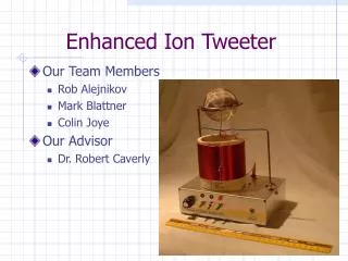
Enhanced Ion Tweeter • Our Team Members • Rob Alejnikov • Mark Blattner • Colin Joye • Our Advisor • Dr. Robert Caverly
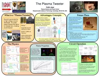
Project Objectives • What did we do? • Created an audio transducer that offers the same frequency content in all directions. • Concentrated on high frequencies since they tend to beam the most. • How we did it: The Ion flame • What is it? • Voltage --> flame size --> sound • Existing devices use vacuum tubes, creating excessive heat • Goal • Raise power efficiency • Decrease unit cost
Presentation Objectives • Intro, Audio Subsystem – Rob • High Voltage Generation – Mark • Results and Conclusions – Colin
The Audio Subsystem • Need • Ion tweeter cannot implement low frequencies --> Filter • Output of source device (CD, cassette) up to 1 V; power rail modulation requires ~ 30 V --> Gain • Design Criteria • Flat frequency response for high audio frequencies • Sufficient gain on signal passed to high voltage circuit
The Audio Subsystem • 3-stage implementation • Buffer for high input impedance • Low Pass • High Pass • Performance measures • Cutoff at 4 kHz and 40 kHz • Total gain factor up to 60
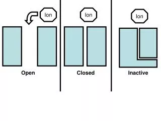
High Voltage Circuit Operation • Generates high voltage necessary for Corona Discharge • Major Components • Power MOSFET • MOSFET Gate Driver • Coil • Uses Resonant Properties of Coil to produce High Voltages • Self-Oscillating nature of circuit provides resilience to environmental changes
Coil Implementations • Keys to producing High Voltage • Resonant Frequency between 3MHz and 8MHz to avoid audible hiss and limitations of technology • High Quality Factor (Q) causes near open circuit • Low DC resistance
Coil Implementations • 10 Coils Built and Tested • Built with Varying Specs • Dimension, wire gauge, and number of turns • Coil Chosen • 16 Gauge Wire • 45 Turns • 5 MHz Resonance • D=3” H=2.5”
Field Effect Transistor (FET) • FET rapidly switches a small current in the coil. • Optimal FET • High Voltage handling • >500 volts • High Transconductance • Greater current in coil • Low Gate Capacitance • <500 pico-Farads • Reduces stress on Gate Driver
Interface Methods • Numerous Approaches Tried and Tested • Pulse Width Modulation (PWM) via Gate Driver • Power Rail Modulation via Audio Transformer • Ground Rail Modulation via Audio Transformer • Faraday Shield Modulation
Interface Methods • Decided on Power Rail Modulation • PWM unable to obtain clean waveforms and oscillations • Faraday Shield requires very High Voltages
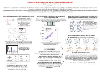
Noise versus Coil Frequency • Flame Flicker Noise present up to 3MHz, as noted by Siegfried Klein in 1956. • This noise is virtually inaudible 7MHz and up. • At 30MHz, the flame has a different appearance and no noise.
Testing • Power Efficiency Test • Tube-based: • 114W at 1cm flame height. • FET-based: • 67W at 1cm flame height. • 40% Power savings
Unit Cost • Unit Cost (45% savings): • FET: $48.46 (to us), $65.44 (industry) • Tube: $120.53 • Total man-hours: • 750 man-hours • Estimated industry cost: • $45,270
Recommendations • For Increased Linearity: • Pulse Width modulation of the FET. • Requires high speed, high precision circuitry. • Requires virtually zero extra power. • Occupies almost no space. • Faraday Shield Modulation. • Affects the voltage gradient directly. • Requires high voltage audio. • Increase operation frequency • Increase flame power
In Conclusion • Special Thanks to: • Texas Instruments (gate drivers) • BGR-WYK Distributors (ST FETs) • International Rectifier (FETs) • Fairchild Semiconductors (FETs) • Alpha Industries (diodes) • Join us for a demo in CEER 210. • Questions????