Download
1 / 45
450 likes | 482 Views
Explore electron acceleration and transport in microwave flaring loops through high-resolution observations, spectral distributions, and modeling simulations. Discover insights from studies on brightness and spectral index distributions.

E N D
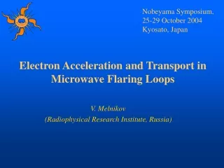
Nobeyama Symposium, 25-29 October 2004 Kyosato, Japan Electron Acceleration and Transport in Microwave Flaring Loops V. Melnikov (Radiophysical Research Institute, Russia)
Nobeyama Radioheliograph Nobeyama Radioheliograph
Microwave flaring loops studies and their implication for the problem of Electron Acceleration and Transport • The first works on microwave flaring loops using observations with high spatial resolution discovered two kinds of microwave sources: • - single compact loop-top sources and • double sources with their peaks located close to theconjugate magnetic footpoints. • (Marsh and Hurford(1980), Kundu et al.(1982), • Kawabata et al. (1982), Nakajima (1983))
Several new studies were published during last years developing further understanding of the problem: Hanaoka 1997; Nishio et al 1997 - footpoint and asymmetric sources Bastian et al. 1998, - a review Lee et al 2000, - dynamics of spectral properties, electron anisotropy Kundu et al 2001, - microwave brightness distribution in limb loops Altyntsev et al. 2002, - subsecond sources Melnikov et al. 2002, - looptop source and inhomogeneity of electron distribution White et al. 2002 - modeling and derivation of microwave source parameters Lee et al. 2002 – electron transport in two interacting loops Yokoyama et al. 2002, - spectral index distribution along a loop Fleishman & Melnikov 2003, - influence of electron pitch angle anisotropy Melnikov et al 2004, - dynamics of brightness distribution along a loop Karlicky 2004 – looptop source on the postflare phase Su & Huang 2004 – polarization of looptop and footpoint sources …
This talk will be restricted mainly to properties of single well resolved loop-like microwave sources. • Microwave brightness distribution along a flaring loop; • Spectral distribution along a flaring loop; • Model simulations of high energy electron distributions along a loop and their GS-emission; • Dynamics of the brightness and spectrum slope distribution along a flaring loop; • Gyrosynchrotron emission from anisotropic electron distributions and its applications (intensity and spectral index distributions).
Loop top source in the event 12 Jan 2000 (a limb flare) • Red area – brightness distribution • at 34 GHz. • Contours: • - dark – hard X-ray emission • (HXT/M2); • light – 17 GHz radio emission • (NoRH)
Radio brightness and magnetic field distributions (a disk flare)
Microwave brightness distribution along flaring loops (f = 34 GHz). Melnikov, Reznikova, Shibasaki 2004
Disagreement with the existing microwave loop models The brightness peaks of optically thin GS emission have to be near the footpoints of extended loops with a nonuniform magnetic field as shown by Alissandrakis and Preka-Papadema (1984), Klein et al (1984) due to strong dependence of GS intensity on the magnetic field strength. Forexample, if the electron power law spectral index =4, then The possibility to have a hump in brightness near the loop topdue to the effect of optical thick emission (Preka-Papadema & Alissandrakis 1992, Bastian et al 1998)is ruled out in our case sincefor all the events under study the frequency spectral index between 17 and34 GHz is negative and, therefore, the microwave emission from the loops isoptically thin at least at 34 GHz.
Attempts to reconcile existing models with NoRH observations 12 Jan 2000 (a limb flare) Middle panel : Spatial profiles of the constant field best-fit models as a function of distance along the loop. Bottom panel: for inhomogeneous magnetic field and differenttransverse dimensions of themodel loop at 17 and 34 GHz (to get them both optically thick). Kundu, Nindos, White & Grechnev, 2001
Time Delays of Emission From the Loop Top 13 March 2000 • The burst of emission from the loop top is delayed against the burst from the footpoint source by several seconds. This delay is more pronounced at 34 GHz than at 17 GHz. • Time profiles of emission from the loop top are wider and their decay is slower than those from the region near the footpoint. 17 GHz, I 17 GHz, V 34 GHz, I
Time delays of emission from the loop top 28 August 1999 • There is almost no delay between the time profiles from the regions near two conjugate footpoints. • For all the events the flux peaks from footpoint sources are coincident in time with the flux peaks of hard X-ray emission (in Fig. the vertical line indicates the moment of the hard X-ray emission peak) • Time delays indicate the trapping and accumulation of high energy electrons in the upper part of an extended loop and lack of these processes near footpoints. • (Melnikov, Reznikova, Yokoyama, Shibasaki, 2002).
Time delays at higher frequencies 13 March 2000 • The peak of the emission at higher frequency, 34 GHz, is delayed against that at 17 GHz. • This is well pronounced for the loop-top part of the sources. However, there are no such well seen delays for the footpoint parts. • The footpoint emission at both frequencies peaks almost simultaneously with the peak of the corresponding hard X-ray burst. Interpretation:Delays at higher frequencies from the looptop can be explained by longer lifetime of the trapped higher energy electrons responsible for the higher frequency emission (Melnikov & Magun, 1998). The absence of the similar delay in the footpoint source excludes the origin of the delay in the looptop due to electron spectral hardening during the acceleration process itself.
We suggest that the probable explanation of the loop-top sourceis trapping, accumulation and, as a result,an enhanced density of mildly relativistic electrons in the upper part of a flaring loop..
Kinetics of Nonthermal Electrons in Magnetic Loops In a magnetic loop part of injected electrons are trapped due to magnetic mirroring and the other part precipitates into the loss-cone. A real distribution strongly depends on the pitch-angle dependence of the injection function S(E,,s,t). Fokker-Plank equation:
Kinetics of Nonthermal Electrons in Magnetic Loops If the energy of electrons E > 200 keV, their lifetime, , in a magnetic trap with n0=1010cm-3is more than 50s. So, if their injection isimpulsive, t < , thecollisional terms in the Fokker-Plank equation can be omitted and the exactsolution can be represented as follows.
Model of a microwave source Magnetic field distribution: B(s) = B0(1+s2/s02) Nonthermal electrons: - power law energydependence:g(E) = g0 E- - pitch-angle distributions: 1. Beam-like distribution: (0) = exp[-(1-02)/12] 2. Isotropic pitch-angle distribution 0 = C = const 3. Pancake distribution: (0) = exp[02/ 12]
Calculations of gyrosynchrotron emission from the model source For calculations of gyrosynchrotron emission we use exact expressions for absorption and emission coefficients in the magnetized plasma (Eidman 1958, 1959; Ramaty 1969; Fleishman & Melnikov, 2003).
Results of simulations Beam-like injection Isotropic injection Pancake injection Melnikov V.F., Shibasaki K., Reznikova V.E. ApJ, 2002,580, L185
These results were obtained only for the loops close to the limb, where the effect ofmagnetic field inhomogeneity is most strong. For calculations we choosed theangle between the magnetic field vector and line of sight =80o. Forthis case two strong peaks of radio emission are observed even for the isotropic injection while the well defined peak of the number density exists in the loop cente. Only in the case of the pancake injectionwe can get a pronounced radio brightness peak at the center of a limb loop. A degree of brightness concentration to the loop center (theratio ILT/IFPcan vary in a wide range depending on the parameter 0 of the gaussian distribution function.
What is the physical reason for the existence of microwave loop-top sources? We consider that the most probable explanation of the loop-top source is a strong concentration of mildly relativistic electrons in the upper part of a flaring loop.. It follows from our simulations that this strong concentration can occur due to the perpendicular to magnetic field pitch-angle anisotropy of high energy electrons. These findings put important new constraints on - the particle acceleration/injection mechanisms and - the kinetics of high energy electrons in flaring magnetic loops.
What acceleration+injection mechanisms can produce anisotropic distributions perpendicular to magnetic field? Indeed: This conclusion is in disagreement with the current theoretical ideas on particle acceleration process in solar flares - DC-electric field (along the loop axes) acceleration, - stochastic MHD-turbulent cascade acceleration in which the acceleration occurs along the magnetic field lines. On the other hand, the mechanisms like the acceleration in current sheets (e.g. Syrovatskii, Litvinenko and Somov, Somov and Kosugi, 1997) look quite favorable to produce highly anisotropic electron distributions near the looptop. I would also mention the model proposed by Vlahos et al., 2004. As well, all types of the betatron mechanism, for instance, considered by Karlicky and Kosugi, 2004, also agree with our finding.
A New approach to an old problem(L. Vlahos, 2004) • From one current sheet to millions
Betatron Acceleration in Collapsing Magnetic Trap(Karlicky, Kosugi, 2004)
What’s about transport effects? • The second possibility to get anisotropic distribution of electrons is some transport effects: • Enhanced pitch-angle scattering and energy losses near footpoints due to • higher plasma density in the lower parts of a loop; • enhanced level of whistler (or some other) turbulence. • This is under consideration now (based on the F-PEq) • In this case we expect some dynamics or redistribution of the microwave brightness along the flaring loop: In the beginning of a burst the regions which are closer to footpoints should be relatively brighter than the looptop.
Some new constraints on the acceleration/transport models following from spatial distribution dynamics Let’s consider temporal variations of 1) the radio brightness and 2) frequency spectral slope distributions along a microwave flaring loop
High frequency spectral index variations along a loop. Yokoyama et al. 2002, ApJ, 576, L87.
High frequency spectral index variation along a loop (Melnikov, Reznikova, Yokoyama, Shibasaki, 2002).
High frequency spectral index variation along a loop We have confirmed the result by Yokoyama et al (2002) that Microwave spectrum near footpoints is considerably softer (by ~ 0.5-1) than near the loop top during the main peak of the bursts under our study
High frequency spectral index variation along a loop • ||decreases in the rise and decay phases of the bursts both near footpoints and near the looptop (in agreement with the result by Melnikov & Magun 1998 obtained without spatial resolution); • A new finding: the decrease of||(flattening of the microwave spectrum) during the decay phase goes remarkably faster in the regions close to the footpoints than near the loop top.
Brightness distribution dynamics, 13 March 2000 Melnikov, Shibasaki, Reznikova, ApJ, 2002 Melnikov, Reznikova, Shibasaki, ApJ, 2004
Brightness distribution dynamics, 24 August 2002 (main peak, 34 GHz)
The microwave brightness along the flaring loop is not constant: - In the beginning of a burst the regions which are closer to footpoints are relatively brighter than the looptop. - In the burst maximum and on the decay phase the situation changes to the opposite. The ratio of the intensities Ilt/Ifp is always higher for 34 GHz than for 17 GHz. Possibly it means that higher energy electrons are more concentrated to the looptop than less energetic ones. In the other words, they are more anisotropic perpendicular to magnetic field.
Some transport effects? • We expect some dynamics or redistribution of the microwave brightness and spectrum along the flaring loop because of enhanced pitch-angle scattering and energy losses near footpoints due to • higher plasma density in the lower parts of a loop; • enhanced level of whistler (or some other) turbulence. • This is under consideration now (based on solving the Fokker-Plank Equation for the non-stationary case).
Model simulations of the GS-spectrum from electrons with pitch-angle anisotropy(Fleishman & Melnikov, ApJ 2003)
Spectral slope at high frequencies • N=kE- -power law electron distribution • J ~ f- - frequency spectrum Synchrotron emission (s>100, E/mc2>>1) = (-1)/2 (Korchak and Terletskii 1952; Getmantsev 1952) Gyrosynchrotron emission (s<100, E/mc2<1) = 0.90 -1.22(Dulk and Marsh 1982)
Influence of the electron distribution anisotropy on the frequency spectrum The angular width of the emission beam: ~ -1 = mc2/E In ultra-relativistic limit (-1 << 1), the anisotropydoes not change the emission spectrum. For solar flare conditions, the broad band microwave emission are mainly generated by mildly relativistic electrons the anisotropydoes influence the emission spectrum.
Model • Since our goal is to reveal the proper effect of the pitch-angleanisotropy on the gyrosynchrotron emission, • we consider : • - a uniformsource with • a constant magnetic field and • time-independent distributionof fast electrons. • For calculations we used exact expressions for absorption and emission coefficients in the magnetized plasma (Eidman 1958, 1959; Ramaty 1969). (Fleishman & Melnikov, ApJ 2003)
1. Power-law distribution of electrons over momentum: 2. Pitch-angle distribution of the sin-N type: 3. Pitch-angle distribution of the gaussian type:
Results of simulations(for the case of rarefied plasma, p/B = 0.3) • Electron pitch-angle • distribution of the sin-N type. • We see considerable change of microwave parameters with for the quasi-parallel propagation • ( =0.8): • a) decrease of intensity; • increaseof the degree of polarization and • Increase of the spectral index • Spectral index approaches the relativistic limit from above.
Results of simulations:2. Electron pitch-angle distribution of the loss-cone type: • f2() ~ exp{-2/ 02} • = cos(), =B^V. In this case we see much stronger dependence of all emission parameters on the anisotropy compared withthe sin-N pitch-angle distribution is clearly seen. Spectral index approaches the relativistic limit from above.
Implications for the observed spectralindex and intensity variations The results presented show clearly that a pitch-angleanisotropy can make an important contribution to the observed spectralindex and intensityvariations in the optically thin part of the spectrum. For the disc flares the foot-point sourceis observed at aquasiparalleldirection, while the loop-top source is observed at a quasitransversedirection. Since anisotropic distributionsprovide systematically softer spectra and lower intensityof gyrosynchrotronradiation (at quasiparallel directions, the case of the foot-point source)than the isotropic or weakly anisotropic distribution (at quasitransversedirections, the case of the loop-top source), this agrees well with theNobeyama Radioheliograph data.
Conclusions • We have shown that the microwave looptop sources indicate on strong concentration of mildly relativistic electrons in the upper part of a flaring loop. • The strong concentration is connected with the perpendicular to magnetic field pitch-angle anisotropy of high energy electrons. • The microwave brightness along the flaring loop is not constant: In the beginning of a burst the regions which are closer to footpoints are relatively brighter than the looptop. In the burst maximum and on the decay phase the situation changes to the opposite. • Pitch-angle anisotropy of high energy electrons can influence significantly the intensity, spectrum and polarization along a microwave flaring loops. • All these findings put important new constraints on the particle acceleration/injection mechanisms and on the kinetics of high energy electrons in flaring magnetic loops.