Download
1 / 13
140 likes | 268 Views
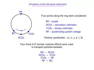
Impedance simulations of the LHC beam screen including the weld. Preliminary analysis C. Zannini, E . Metral, G. Rumolo, B. Salvant . Model studied. LHC design as it is built and installed. In this step we are only interested to understand the effect of the weld . weld. Model studied.

E N D
Impedance simulations of the LHC beam screen including the weld Preliminary analysis C. Zannini, E. Metral, G. Rumolo, B. Salvant
Model studied LHC design as it is built and installed In this step we are only interested to understand the effect of the weld . weld
Model studied a=46.4 mm b=36.8 mm w=2 mm L=1m w b a L
Comparing dipolar terms xdip weld 2*xdip_noweld xdip 2weld 2*xdip_weld
Impedance simulations • With CST Particle Studio we obtain the dipolar wake potential at different beam positions • Via CST FFT for each wake potential we obtain the real and imaginary dipolar impedance and then the real and the imaginary dipolar impedance versus beam position • The dipolar components of the impedance is the slope of these curves in the linear region • We are interested specially at the impedance at 40MHz and 8KHz • β=1 40MHz 7.5m 25ns • β=1 8KHz 32.5Km 0.125ms • To have impedance simulations at these frequency we need to reach these frequency (simulating a sufficiently long wake) and to have vanish wake (to make a good FFT).
The scaling technique • If we use the real dimension of the beam-screen it is impossible to go down in frequency until 8KHz. • To keep the same electromagnetic configuration we can scale by the same factor all the geometrical parameters and the skin depth. Example Parameters: Scaled parameters: S=1 mm k=1000 S=1000 mm σ=1e9 S/m σ=1e3 S/m
The scaling technique work very well: Comparing 20Km (k=1000) 100Km (k=10000)1000Km (k=100000)
Comparing with and without weld dipolar impedance in the range 1KHz-50MHz calculating for a displacement of 5mm
Comparing with and without weld dipolar component of the impedance in the range 1KHz-50MHz calculating from the slope in the range 0-5mm
Obtaining dipolar components at 40MHz Real dipolar impedance with weld 2*Real dipolar impedance without weld Imaginary dipolar impedance with weld 2* Imaginary dipolar impedance without weld
Obtaining dipolar components at 8KHz Real dipolar impedance with weld 1.2*Real dipolar impedance without weld Imaginary dipolar impedance with weld 1.5* Imaginary dipolar impedance without weld
Conclusions • At the frequency of 8KHz a weld of 2mm introduces a factor 1.2 on the dipolar real impedance and a factor 1.5 on the dipolar imaginary impedance. • At 40MHz a weld of 2mm introduces a factor 2 in the dipolar real and imaginary impedance
Future step • To calculate the quadrupolar component of the impedance.