Computer Components & Architecture
Explore components of a modern computer system, program execution, assembly process, and basic architecture concepts. Discover CPU basics, registers, ALU operations, buses, and bus types. Learn the importance of control and data flow in computer systems.

Computer Components & Architecture
E N D
Presentation Transcript
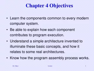
Chapter 4 Objectives • Learn the components common to every modern computer system. • Be able to explain how each component contributes to program execution. • Understand a simple architecture invented to illuminate these basic concepts, and how it relates to some real architectures. • Know how the program assembly process works. Lecture
Introduction • In Chapter 2, we discussed how binary-coded data is stored and manipulated by various computer system components. • In Chapter 3, we described how fundamental components are designed and built from digital circuits. • Also from Chapter 3, we know that memory is used to store both data and program instructions in binary • Having this background, we can now understand how computer components are fundamentally built • The next question is, how do the various components fit together to create useful computer systems. Lecture
Basic Structure of Computers Coded info is stored in memory for later use Program is stored in memory and determines the processing steps Input unit accepts code info from human operators, electromechanical devices (ie keyboard), other computers via networks ALU uses the coded info to perform the desired operations All actions are coordinated by the control unit The output unit sends the results back out externally Collectively called the I/O unit Collectively called the processor Lecture
CPU Basics • The next question is, how is the program EXECUTED and how is the dataPROCESSED properly ? • The computer’s CPU or Processor • Fetches the program instructions, • Decodes each instruction that is fetched , and • Perform the indicated sequence of operations on the data (execute) • The two principal parts of the CPU are theDatapathand theControl unit. • Datapath - consists of an arithmetic-logic unit (ALU) and network of storage units (registers) that are interconnected by a data bus that is also connected to main memory. • Control Unit - responsible for sequencing the operations and making sure the correct data is in the correct place at the correct time. Lecture
CPU Basics • Registers hold data that can be readily accessed by the CPU – data like addresses, program counter, data, and control info • Registers can be implemented using D flip-flops. • A 32-bit register requires 32 D flip-flops. • There are many different registers – • to store values, • to shift values, • to compare values, • registers that count, • registers that temporary store values, • index registers to control program looping, • stack pointer registers to manage stacks of info for processes, • status or flag registers to hold status or mode of operation, • and general purpose registers Lecture
CPU Basics • The arithmetic-logic unit (ALU) carries out • logical operations (ie. comparisons) and • arithmetic operations (ie. adding or multiplying) • The ALU knows which operations to perform because it is controlled by signals from the control unit. • The control unit determines which actions to carry out according to the values in a program counter register and a status register. • The control unit tells the ALU which registers to use and turns on the correct circuitry in the ALU for execution of the operation. • The control unit uses a program counter register to find the next instruction for execution and uses a status register to keep track of overflows, carries, and borrows. Lecture
The Bus • The CPU shares data with other system components by way of a data bus. • A bus is a set of wires that simultaneously convey a single bit along each line. • One or more devices can share the bus. • The “sharing” often results in communication bottlenecks • The speed of the bus is effect by its length and the number of devices sharing it Lecture
The Bus • Two types of buses are commonly found in computer systems: point-to-point, and multipoint buses. • Point-to-point bus connects two specific devices • Multipoint buses connects a number of devices. Because of the sharing, a bus protocol is used. Lecture
The Bus • Buses consist of data lines, control lines, and address lines. Address lines determine the location of the source or destination of the data. Data lines convey bits from one device to another. Moves the actual information that must be moved from one location to another. Control lines determine the direction of data flow, and when each device can access the bus. • When sharing the bus, concurrent bus requests must be arbitrated. • Four categories of bus arbitration are: • Daisy chain: Permissions are passed from the highest-priority device to the lowest. • Centralized parallel: Each device is directly connected to an arbitration circuit. • Distributed using self-detection: Devices decide which gets the bus among themselves. • Distributed using collision-detection: Any device can try to use the bus. If its data collides with the data of another device, it tries again. Lecture
Types of Buses • Processor-memory bus – short high speed bus used to transfer to and from memory • I/O buses – longer buses that interface with many I/O devices other than the processor • Backplane bus (or system bus) – connects the processor, I/O devices and memory. • Expansion bus – connect external devices • Local bus – a data bus that connect a peripheral device directly to the CPU • Buses from a timing perspective: • Synchronous buses - work off clock ticks – all devices using this bus type are synchronized by the clock rate • Asynchronous buses – control lines coordinate the operations and a “handshaking protocol” is used for the timing. These types of buses can scale better and work with more devices Lecture
Clocks • Every computer contains at least one clock that: • Regulates how quickly instructions can be executed • Synchronizes the activities of its components. • A fixed number of clock cycles are required to carry out each data movement or computational operation. • As a result, instruction performance is measured in clock cycles. • The clock frequency, measured in megahertz or gigahertz, determines the speed with which all operations are carried out. • Clock cycle time is the reciprocal (or inverse) of its clock frequency. • An 800 MHz clock has a cycle time of 1.25 ns. • Clock speed should not be confused with CPU performance. • The CPU time required to run a program is given by the general performance equation: • We see that we can improve CPU throughput when we reduce the number of instructions in a program, reduce the number of cycles per instruction, or reduce the number of nanoseconds per clock cycle. Lecture
The Input/Output Subsystem • A computer communicates with the outside world through its input/output (I/O) subsystem. • Input device examples: keyboard, mouse, card readers, scanners, voice recognition systems, touch screens • Output device examples: monitors, printers, plotters, speakers, headphones • I/O devices connect to the CPU through various interfaces. • I/O can be memory-mapped-- where the I/O device behaves like main memory from the CPU’s point of view. • Or I/O can be instruction-based, where the CPU has a specialized I/O instruction set. Lecture
MARIE • Up to this point, we have discussed: (1) the CPU in general, (2) the ALU, (3) the Control Unit, (4) the Bus, (5) the Clock, (6) the I/O subsystem, and (7) Memory and Addressing • We can now bring together many of the ideas that we have discussed to this point using a very simple computer architecture model called MARIE • MARIE stands for the Machine Architecture that is Really Intuitive and Easy. • MARIE was designed for the singular purpose of illustrating basic computer system concepts. • While this system is too simple to do anything useful in the real world, a deep understanding of its functions will enable you to comprehend system architectures that are much more complex. Lecture
MARIE Characteristics MARIE in general consist of a CPU (which contains an ALU and several registers) and Memory (for storing data and programs). The MARIE architecture has the following characteristics: • Binary, two's complement data representation. • Stored program, fixed word length data and instructions. • 4K words of word-addressable main memory (not byte addressable) • 16-bit data words. • 16-bit instructions, 4 bits for the opcode and 12 bits for the address. • A 16-bit arithmetic logic unit (ALU) with seven registers for control and data movement. • Accumulator (AC) • Instruction Register (IR) • Memory Buffer Register (MBR) • Program Counter (PC) • Memory Address Register (MAR) • Input Register • Output Register Lecture
MARIE Registers Registers are storage locations with in the CPU. MARIE’s seven registers are: • Accumulator, AC, a 16-bit register that holds a conditional operator (e.g., "less than") or one operand of a two-operand instruction. • Memory address register, MAR, a 12-bit register that holds the memory address of an instruction or the operand of an instruction. • Memory buffer register, MBR, a 16-bit register that holds the data after its retrieval from, or before its placement in memory. • Program counter, PC, a 12-bit register that holds the address of the next program instruction to be executed. • Instruction register, IR, which holds an instruction immediately preceding its execution. • Input register, InREG, an 8-bit register that holds data read from an input device. • Output register, OutREG, an 8-bit register, that holds data that is ready for the output device. Lecture
MARIE Architecture Depicted ALU carries out the logic operations (comparisons) and arithmetic operations (adding, etc). Each memory location has a unique address. Addresses go from 0 to 4K-1 (which is 4095). Each location can store a 16-bit word Control Unit monitors and control the execution of all instructions and the transfer of all information CU extracts the instruction from memory, decodes the instructions, make sure data is in the right place at the right time, tell the ALU which registers to use, services interrupts, turn on the correct circuitry in the ALU for operation execution Lecture
MARIE Architecture Depicted Accumulator, AC holds a conditional operator (e.g., "less than") or one operand of a two-operand instruction. Output register, OutREG, an 8-bit register, that holds data that is ready for the output device Memory address register, MAR, a 12-bit register that holds the memory address of an instruction or the operand of an instruction Not shown is the Status or Flag register of the ALU that holds info indicating various conditions such as overflows Input register, InREG, an 8-bit register that holds data read from an input device. Memory buffer register, MBR, a 16-bit register that holds the data after its retrieval from, or before its placement in memory. Program counter, PC, a 12-bit register that holds the address of the next program instruction to be executed Instruction register, IR, which holds an instruction immediately preceding its execution. Lecture
MARIE Bus • A Bus is needed to transfer data or instructions into or out of registers • The registers are interconnected, and connected with main memory through a common data bus. • Each device connected to the bus is identified by a unique id or number • Before any device can use the bus, the device’s unique number is set on the control lines to allow that device to carry out an operation. • Separate connections are also provided between the accumulator and the memory buffer register, and the ALU and the accumulator and memory buffer register. • This permits data transfer between these devices without use of the main data bus. Lecture
MARIE Data Path • Also have separate communication or data paths outside of the bus to speed up execution • The benefit is, these paths allow events to occur in parallel • One event can be using the bus • And some other event can using a data path at the same time • Have a communication path between the MAR and Memory • MAR provides the inputs to the address lines for memory • So the CPU knows where to read from or write to memory • Have a communication path from the MBR to the AC • Have a communication path from the MBR to the ALU • Allows data in MBR to be used in arithmetic operations • Also, info can flow from the AC through the ALU and back into the AC without traveling on the Bus • The datapath in general is the path that information follows – the figure depicts MARIE’s datapath Lecture