Download
1 / 33
350 likes | 544 Views
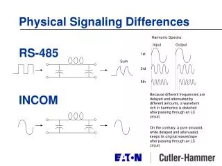
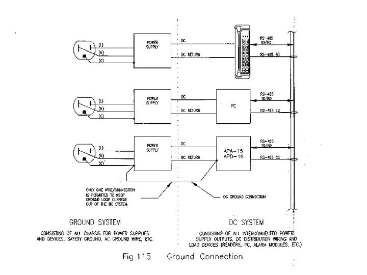
The RS-485 interface supports data rates up to 100k BPS over distances of 4000 feet (1200 meters). A twisted pair cable with 120-ohm impedance is essential, with a maximum length determined by -6dB DC loss for 24 AWG wire and AC signal loss. Shielding improves noise rejection. Apollo equipment utilizes the shield for common mode grounding and noise shielding. Recommended cables are 24 AWG for full specifications; 28 AWG may suffice for shorter distances but can limit future expansion. Proper wiring ensures reliable performance in access control systems.

E N D
RS-485 Cable Requirements The RS-485 interface is capable of a data rate of up to 100k BPS at a distance of up to 4000 feet (1200 meters). A twisted pair cable with impedance of 120 ohms is specified. The maximum distance limit is set by the –6db DC loss for a 24 AWG wire as well as by AC signal loss at the maximum data rate. A shield is typically required for improving noise rejection. Apollo equipment uses this cable shield fro the dual purposes of establishing common mode ground and noise shielding.
Belden Part # Gauge Wire type DC resistance 8132 28 AWG 7 x 36 stranded 65 ohms/1000 ft. 9842 24 AWG 7 x 32 stranded 24 ohms/1000 ft. RS-485 Specifications Summary: Driver loaded output voltage: Rt=54 ohms 1.5 V min. Driver short circuit current: Vout = +12/-7 V 250 ma Driver output common mode: 3 V max. Receiver sensitivity: 200 mv Receiver common mode voltage: +12 V max, -7 V min. Receiver input resistance: 12 K ohms min. Cables specifically designed for the RS-485 interface are available in 24 AWG and 28 AWG, with the 24 AWG meeting the full specification. The 28 AWG cables if suitable for limited span (less than 1000 feet, 300 meters) at reduced cost. If a system has any possibility for future expansion, which may call for extending the communication span, 28 AWG wire should not be used. Cable of 24 AWG is recommended.
Cables NOT specifically designed fro RS-485 interface may be used to interconnect Apollo equipment at reduced performance. This may translate to reduced communication span and reduced number of nodes (number of devices per port). Low capacitance cable with twisted pairs and shield for RS-232/RS-422 may be used. Cable of 24 AWG wire size should have wire to wire capacitance of approximately 12 pf.
Problem - The reader does not honor the exit request. Granting access from card and/or PIN’s functions correctly. - Check the exit push button wiring - For readers with supervised inputs the exit push button must be terminated with the correct EOL terminator. Switching from alarm (10K ohms) to safe (300 ohms) will activate the exit request - Check that the reader is not in a tamper condition. Reader tamper will disable the exit request and it will remain disabled for 1 minute after the tamper condition is cleared. Problem - The door strike only energizes for a short time (1-2 seconds) for an access grant. Setting it longer has no effect. - Check the door contact wiring. If the door contact is not closed, the strike will only be energized for a short time because the door is considered to be already open - For readers with supervised inputs, check for the correct EOL and correct EOL wiring